
")


 Reply With Quote
now look how easy it is to tweek the boost on a 300tdi! if only they came out the factory like that
cheers phil

 Master
Hey,
About time I started posting some pics of my upgrade.
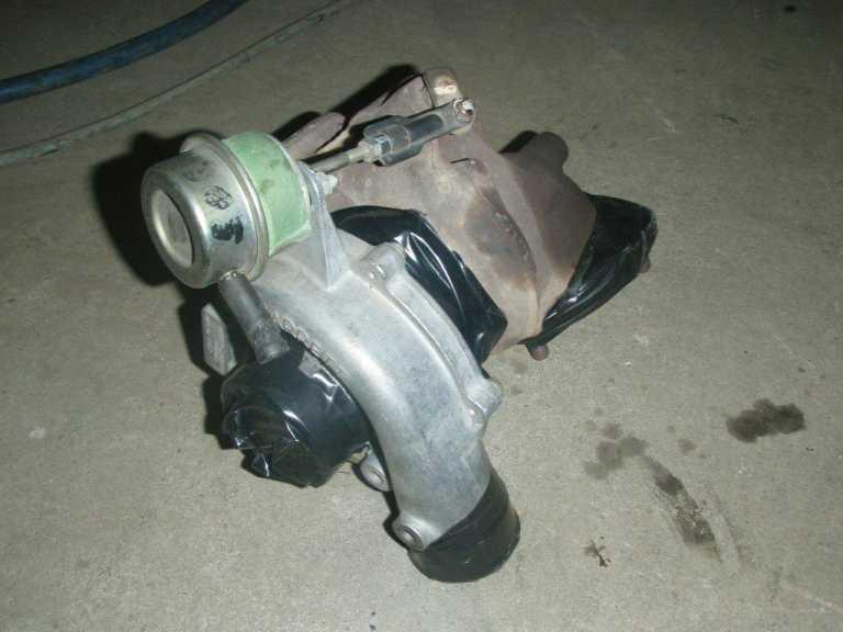
My 300TDI turbo is about dead.
Got a 2003 TD5 Turbo with very low K's for FREE!
The main aim here is to build a custom manifold so I can bolt the TD5 turbo up too the 300TDI Engine. Also have to make custom oil feed lines for the turbo, re route the auto cooler lines and make a custom air intake. As well as modify the dump pie.
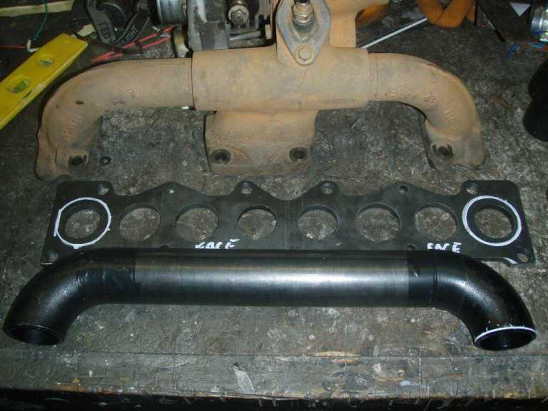
The parts -
had a manifold gasket laser cut to 8mm (should have been more like 12mm)
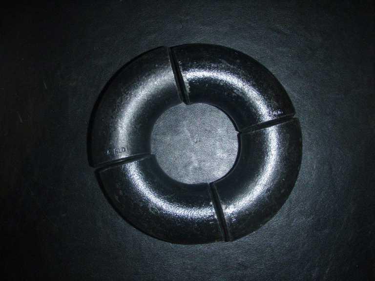
The 90Deg elbows - 40NB 3.6 walls
The Turbo
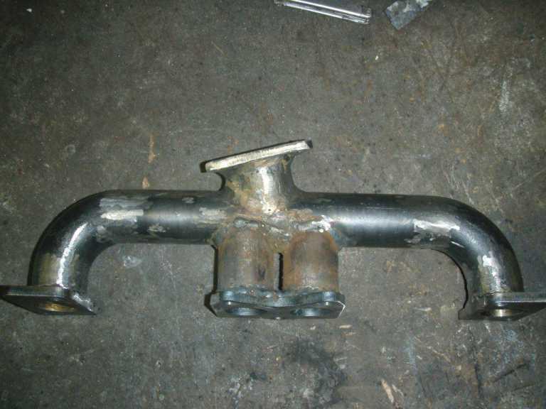
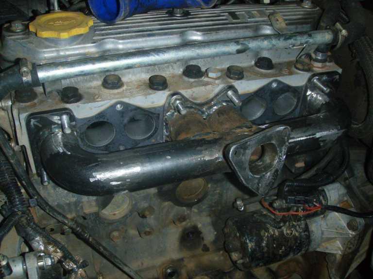
First thing was to make the manifold -
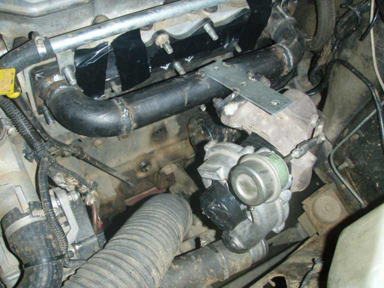
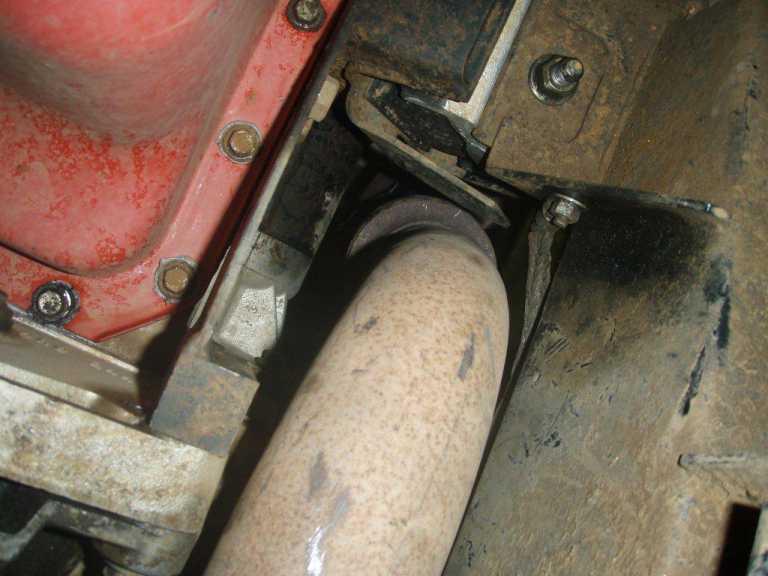
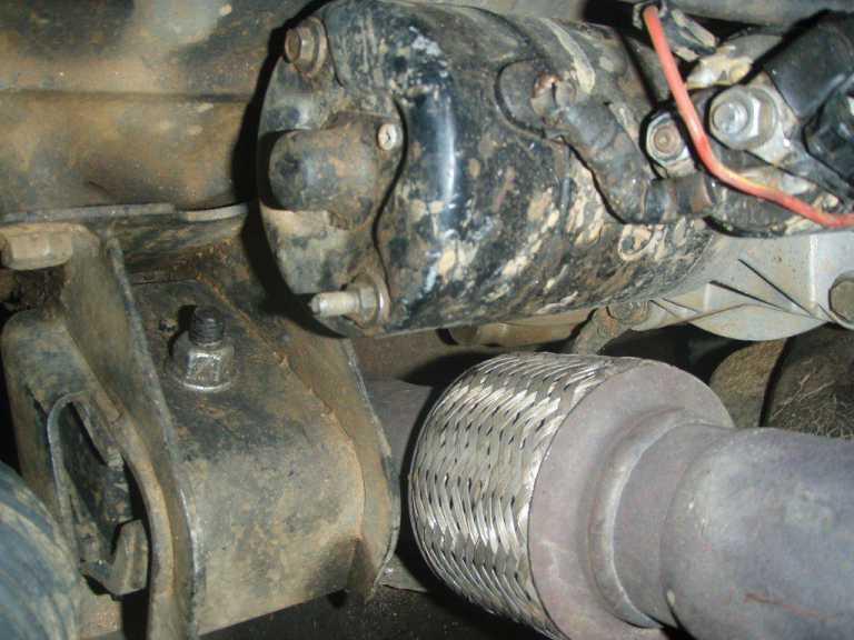
Bolted the bulk of the manifold to the engine then position the dump pipe into the right spot. On the std unit the dump pipe is to the front of the engine mount now it will be to the rear of the engine mount between the firewall and engine mount between the starter motor and the chassis rail.
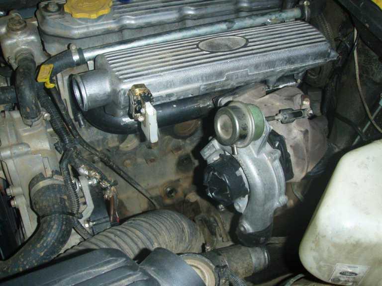
Its tight but it will work
Once it's running it will think about getting a 3" from the turbo back. The flex joint is bigger the 3" and it has room to move so space shouldn't be an issue
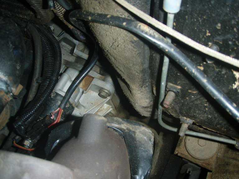
This is as far forward as i can come form the firewall. I am going to get some of that stick on heat shield and line the firewall so i don't get any unwanted heat in the cab (unless anyone has a better idea?)
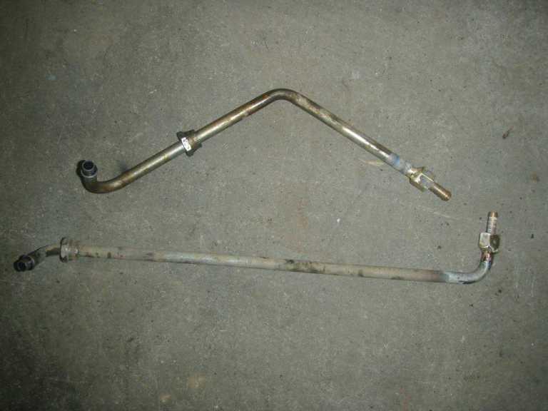
Rather then get new auto lines made up i cut the old ones down and i am going to run 3/8 rubber oil line on top of the chassis rails to keep them away from the heat of the exhaust (unlike the factory ones)
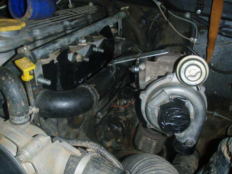
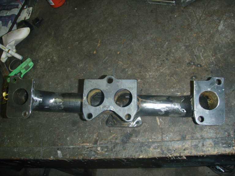
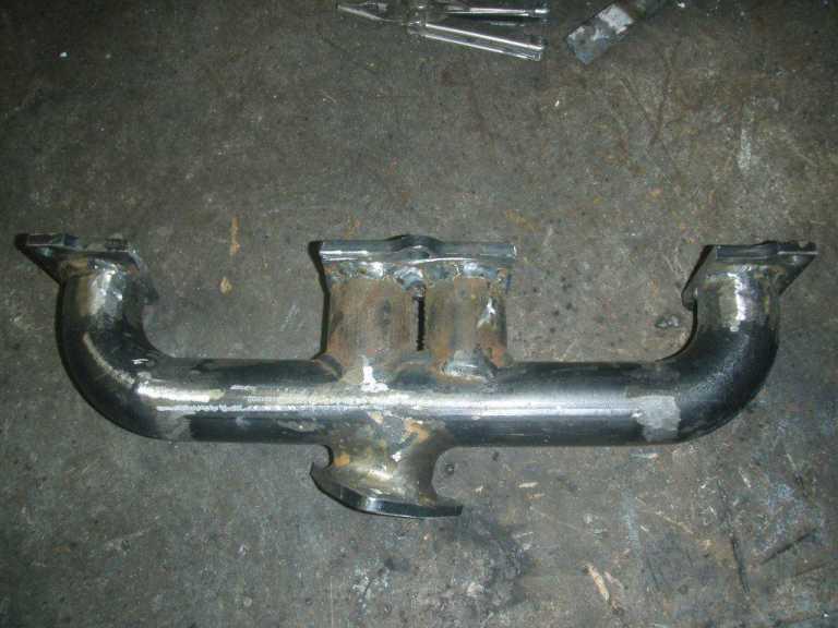
The manifold -
Manifold bolted on -
where the manifold meets the head the plates are only 8mm which IMO is too thin so i am going to weld the spare set of plates i had made up to them so they will be 16MM thick which will bring the turbo out an extra 8mm so it wont be so close to the intake manifold. (the thing hanging off the intake manifold is a pressure switch)
TopicToaster
now look how easy it is to tweek the boost on a 300tdi! if only they came out the factory like that
cheers phil
Master
Yep!!Originally Posted by discowhite

this one came off a disco that had been tweaked already i think it run 22PSI at the intake I am going to turn it down just a little so i don't put a piston out the side of the block!
YarnMaster
That is a lot of work for a TD5 turbo.
22 psi is not going to cause a drama with the 300Tdi. But I believe that compressor is going to be in a poor efficiency area, so there will be little gain over say 18 psi, not considering the extra heat it will be adding to the air, and the high drive pressure in the exhaust manifold.
Master
Was a bit of work but hasn't cost me much. I am not after massive performance hence why I am going to turn it back down. Just needed a new turbo. And this way I have have a manifold that i can bolt a VNT too when one comes along.
Mick
TopicToaster
Well done,
A1 for endeavor. It will be just like a bought one, looks 200 TDi'ish.
Bush65,
How far would you be able to push the 200/300 TDi and TD5 turbos before they fell out of the efficiency contours on the turbo maps? Most maps are norrower on the flow/horse power axis and longer on the pressure axis (I think that is correct) but I guess higher Pressure/boost leads to more HP so it would all be dependant on each other
YarnMaster
I spent a lot of time finding the details of the 200/300Tdi and TD5 turbos, then trying to find the compressor maps.
The turbos are all of similar size. The turbo models changed because of what was current at the appropriate year.
The 200Tdi has a Garrett TB0242 (Defender) or TB0243 (Discovery). The Garrett ident numbers are 465171-0001/2 (Defender) and 465175-0001 (Disco). The centre housing and rotating assembly (CHRA - the bearing housing, shaft and impeller wheels) are identical for both (Garrett part number 443854-0033), so differences will be with the compressor or turbine housings. Turbine A/R is 0.47.
The 300Tdi has a Garrett T250-04. Garrett number 452055-0004. The CHRA part number is 443854-0110. Turbine A/R is 0.47.
The TD5 has a Garrett GT2052. Garrett number 732252-0001. Turbine A/R is 0.46.
I didn't look hard enough for the 200/300Tdi compressor maps.
I didn't find maps that are specifically for the actual TD5 turbo. Garrett listed several variations for the GT2052 in their general catalogue. These would have slight differences to OEM turbos provided to engine manufactures - such as orientation of inlet/outlet etc. But I believe it is reasonable to use the compressor maps.
All GT2052 have a 52mm exducer (outlet), compressor wheel (given by last 2 digits in model number), but they are offered with a range of inducer (inlet) diameter.
Now I don't know what size the inducer is for a TD5, but I have some clues. The 300Tdi has an inducer diameter of approximately 38mm. If the inducer is reduced the air flow rate will be reduced for the same size exducer. It is not likely that a turbo for a TD5 will be selected for a lower air flow than for a 300Tdi. And this is the largest inducer used with the GT2052.
I also did some quick calculations for air flow required for a TD5 to make 100 kW and believe it will be in the order of 20 lbs/min corrected air flow. On this basis comparing the compressor maps, only one looked suitable. BTW, a 300Tdi will require similar air flow to make the same or a little less power.
This compressor map is shown below.
The vertical axis is pressure ratio (PR) this is the ratio of the outlet pressure/inlet pressure. Now these pressures are absolute not gauge pressure. Converting some boost (gauge pressure) to PR gives:
11 psi boost is approx PR = 1.75
15 psi boost is approx PR = 2
18 psi boost is approx PR = 2.25
22 psi boost is approx PR = 2.5
The horizontal axis is the corrected air flow in lbs/minute - my quick calc showed the TD5 will need about 20 lbs/min to make 100 kW with reasonable air/fuel ratio (i.e. no black smoke or high egt).
The left boundary line is the surge line. The right boundary line on the map is the maximum air flow the compressor can deliver for different PR.
The lines that go across between the left and right bounds, are lines of compressor rpm. As can be seen the compressor has to spin faster to produce more boost and or more air flow.
The upper compressor rpm line is the maximum speed that the compressor should be run at (one purpose of a waste gate is to prevent the turbo from over speeding).
The remaining contour lines are compressor efficiency.
The dotted line through the centres of the efficiency contours shows where the compressor is most efficient for combinations of PR and corrected air flow.
It is clear for this compressor map that PR 2.5 (22 psi boost pressure) is off the map.
A TD5 will not spend a lot of it's life running at maximum rpm, so the 20 lbs/min line so far to the right is acceptable. Corrected air flow of 15 lbs/min @ 15 psi boost (PR=2) is in the sweet spot on this map.
For more performance, we need more air flow and boost pressure and we quickly move to regions of lower compressor efficiency as these increase. And for a significant upgrade in performance a different compressor could be required.
I would expect compressor maps for 200/300Tdi turbos to be very similar to this.
TopicToaster
Bush65,
Thank you, it appears that some of it is sinking in. All the references you have posted are starting to make sence. Getting the maps is the bit that is critical.
From what I see of the map at a pressure ratio of 2.5 the turbine will be spinning over 160k rpm. I don't know what a suitable limit for the speed on the turbine would be in this case. With a little exptrapulation of the curves that are there if you could get the turbo spinning over 160k rpm safely as long as you did not run the engine at full rpm then 22 psi would not be that inefficient. The efficency drops as you try and push greater amounts of air through.
How do we handle VNT turbos? I can see that the map is not likely to change as the maps are for the compressor side of the CHRA. The VNT deals with exhaust pressure/temp and turbo rpm like all turbos but alters the geometry (don't know if that is the A/R).
YarnMaster
Grab them with both hands and run
A variable geometry turbine is like having a turbine housing that varies the A/R.
They allow a larger turbine for better performance at higher rpm, but adjust to produce more boost at lower rpm.
The GT2256V variable geometry turbo used on both the disco 3 TDV6 and the HS2.8L that was developed from the 300Tdi. There are some differences in the housings and small details, but basically the same size turbo.
TDV6: Garrett No. 712541-0001/2, CHRA 703891-0037
HS2.8L: Garrett No. 724652-0001, CHRA 703891-0041
These have a larger compressor with a 56mm exducer.
The inducer for the turbo on the HS2.8L turbo is approx 39mm. The following compressor map (the closest I have) is for a compressor on a GT2056 turbo: same 56mm exducer, but slightly larger inducer at 41.5mm. Expect the corrected air flow for the compressor on the HS2.8L turbo to be a little less, and efficiency to be a little better at same PR on this compressor map.
You can see marked improvement in compressor efficiency at 2.5 PR compared to the 52mm compressor on the TD5.
Stock HS2.8L engines run over 22psi boost pressure and this turbo is the main reason the performance of the engine is much better than a 300Tdi. The GT2256V turbo works very well on a 300Tdi.
I don't know what the boost pressure is on disco 3, TDV6, but I wouldn't be surprised if it is similar to 22 psi.
OldBushie
What are you doing to the intercooler? I would have thought the Tdi's would be high enough flow but low on cooling potential.
MY15 Discovery 4 SE SDV6
Past: 97 D1 Tdi, 03 D2a Td5, 08 Kimberley Kamper, 08 Defender 110 TDCi, 99 Defender 110 300Tdi[/SIZE]
 Posting Permissions
| Search AULRO.com ONLY! |
Search All the Web! |
|---|
|
|
|


Bookmarks