Page 4 of 69 FirstFirst ... 234561454 ... LastLast
Results 31 to 40 of 690

Thread: Meet my 90, and share the adventure.

  1. #31
    Join Date
    May 2014
    Location
    Tamworth NSW
    Posts
    4,295
    Total Downloaded
    0
    Quote Originally Posted by ozy013 View Post
    I watched it go all the way down to the creek, and your right they are an amazingly capable rig. I usually only ever see them in the big smoke, what a waste!
    Ps, the double decker exbox is pure genius .

    Cheers, Ian.
    Thanks Ian,
    I was amazed by the level of engineering on the hummer. If anyone sees one, have a closer look, they are a well thought out design.

    Thanks for the feedback on the ex box. Sometimes I surprise myself with my own inventions
    -Mitch
    'El Burro' 2012 Defender 90.

  2. #32
    Join Date
    May 2014
    Location
    Tamworth NSW
    Posts
    4,295
    Total Downloaded
    0

    Winch wiring and solenoid box relocation

    The winch is in, and the wiring is now half done!

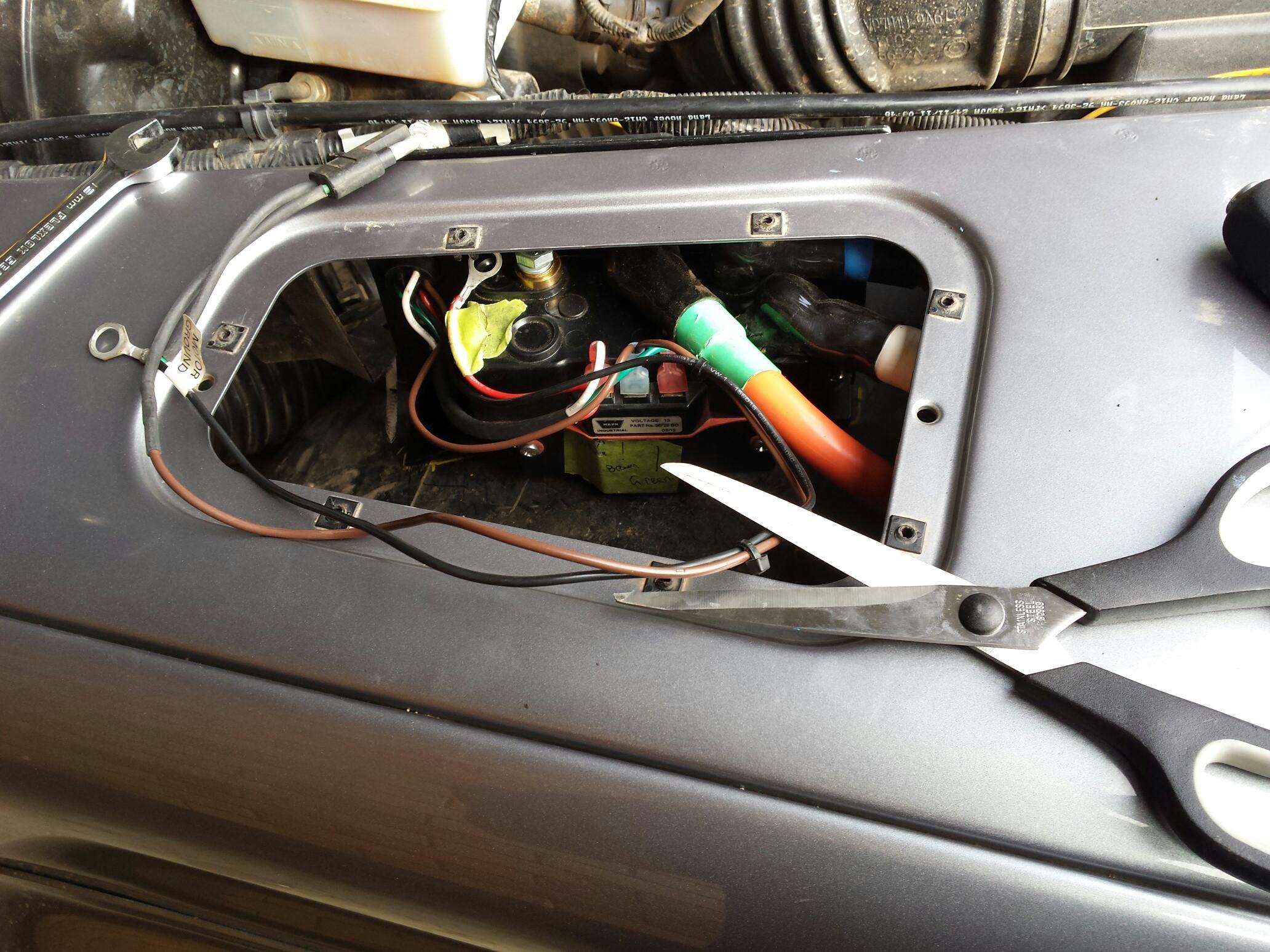
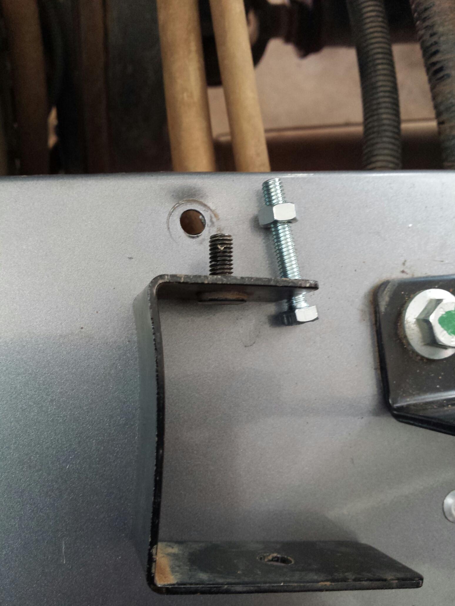
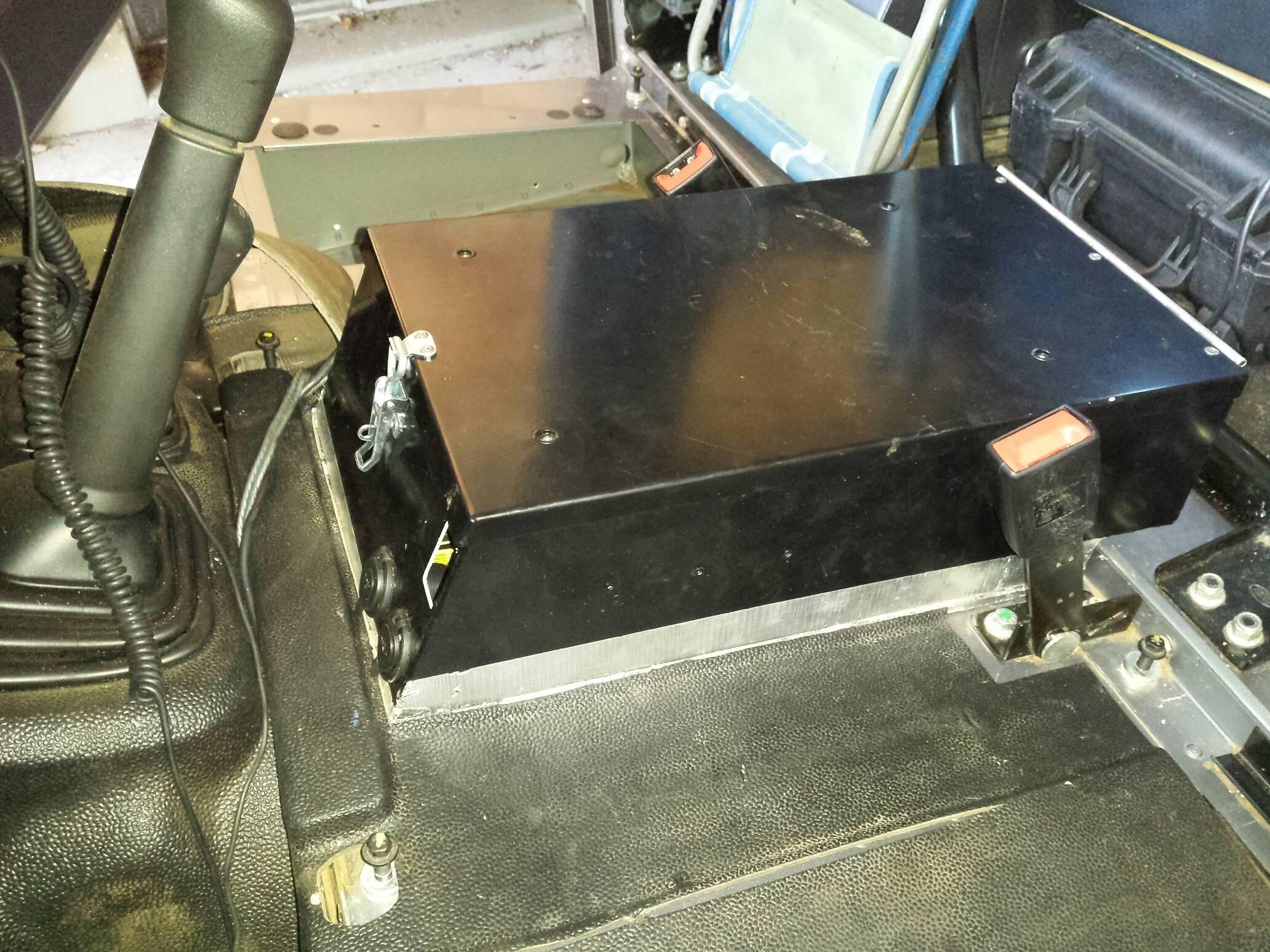
    Back in post 22 and 23 of this thread, I manufactured a bracket to hold the solenoid box for my winch, relocating it to the top of the wheel arch, directly below the false air intake vent on the drivers side wing top. Kudos to Tikka7mm08 whose pic here gave me the idea.

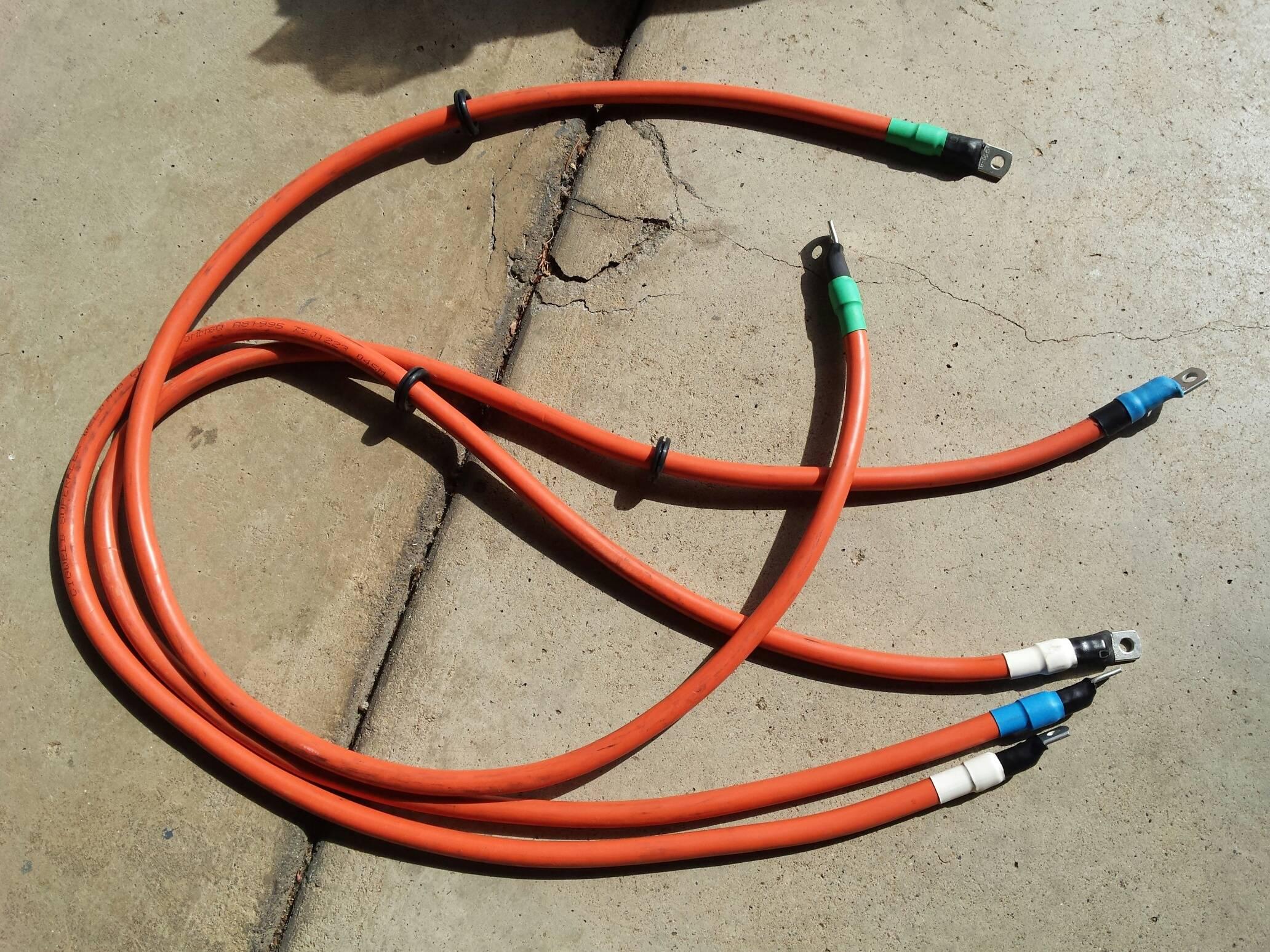
    I opted for 50mm2 welding cable to run from the F1 F2 and A terminals on the winch back to the solenoid box. With the winch in situ, it was an easy task of lining up the wiring and making up the cables (with some extra attention to detail, for good measure). I made all cables 1.3m long, which has plenty of leeway for future winch upgrades if needed. In a pinch having the cables at 1.2m would work fine.


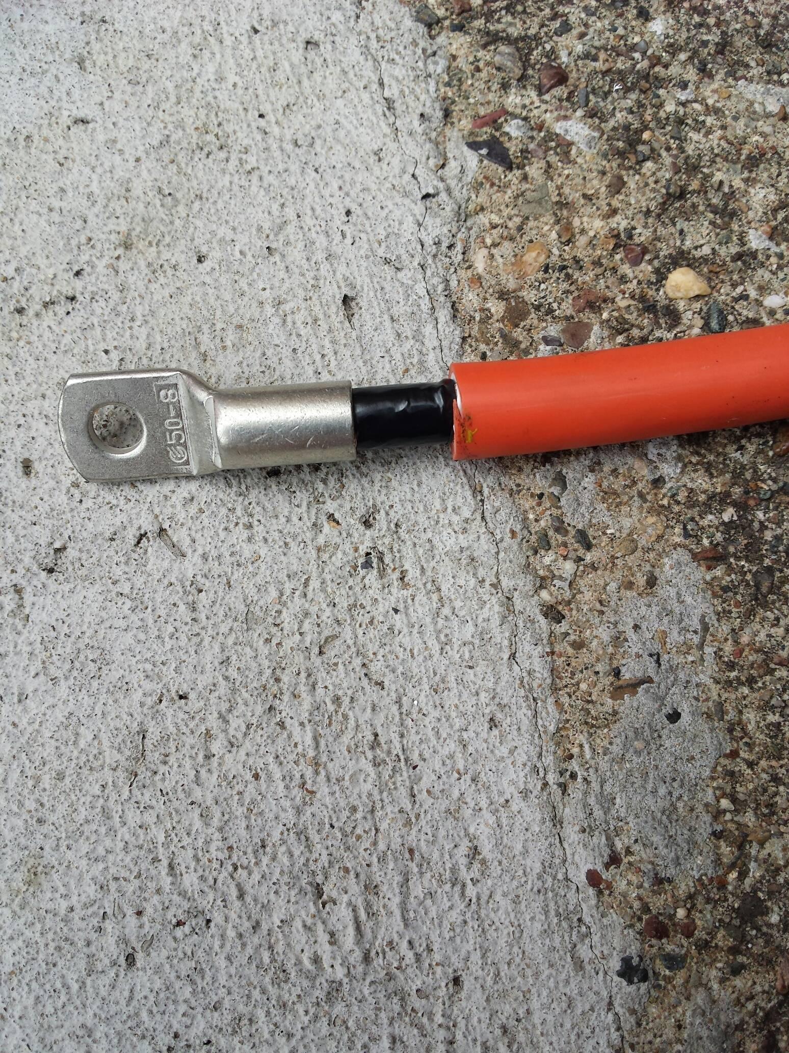
    I used 50-8 lugs for these components. 50mm2 cable, with 8mm lug hole. I crimped them on with a cable lug crimping tool (similar to a set of bolt cutters, but with crimping dies instead of a cutting blade).
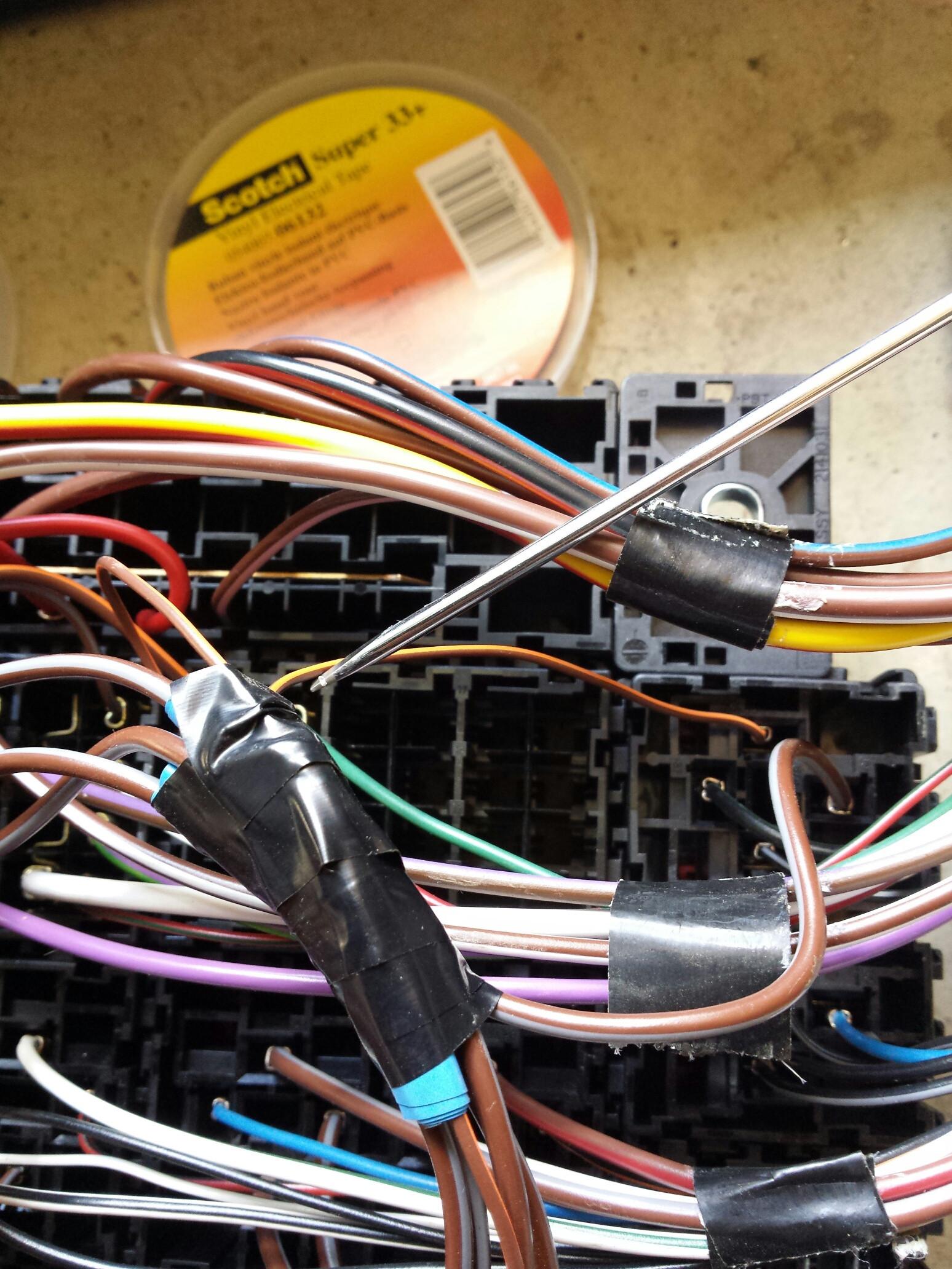
    Sometimes it's a pain in the arse to get the copper strands into the lug. What I do here is wrap some electrical cable around it to tighten it up, then force it all in, then slowly unwrap the tape to get the last bit in.


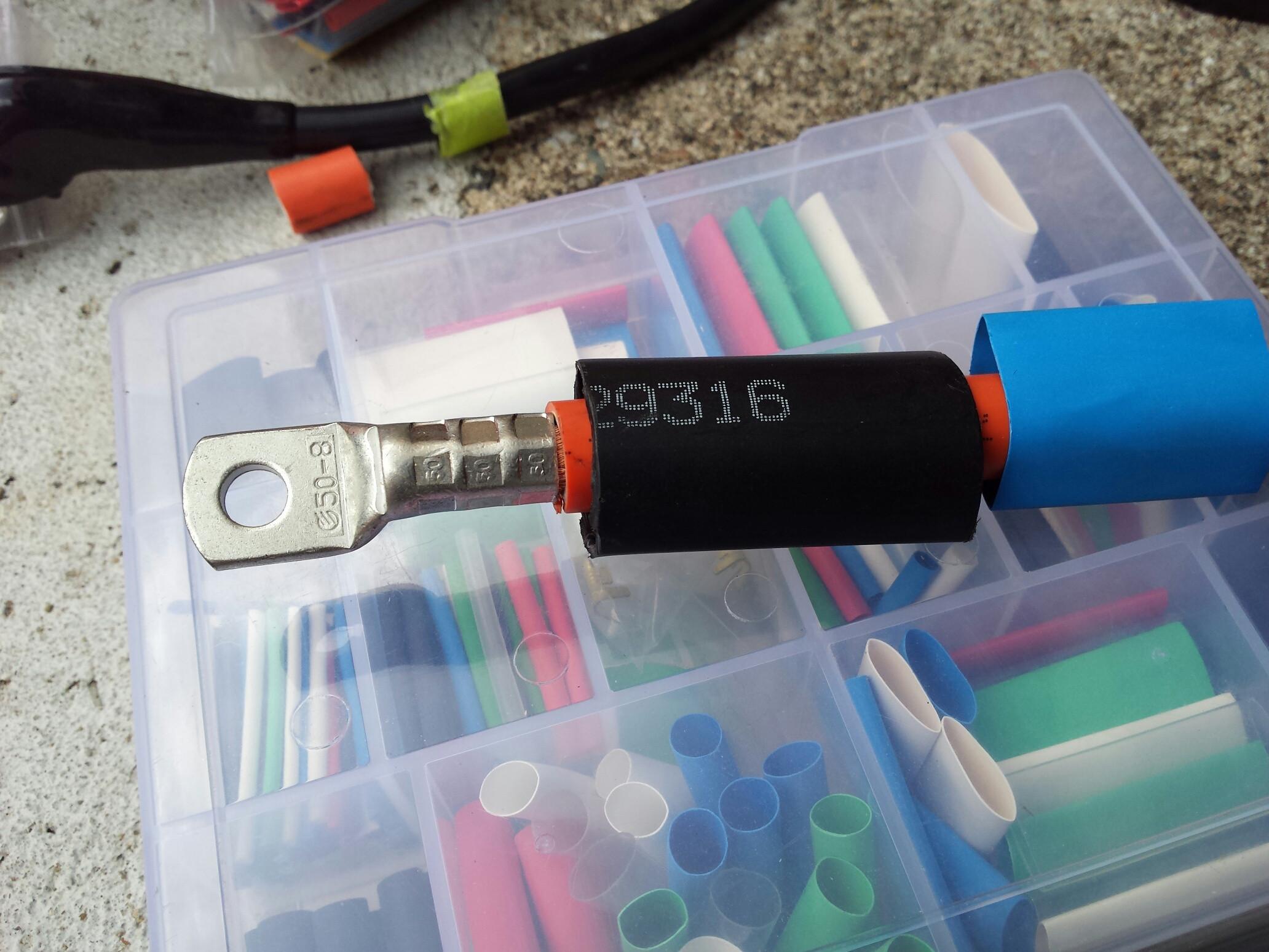
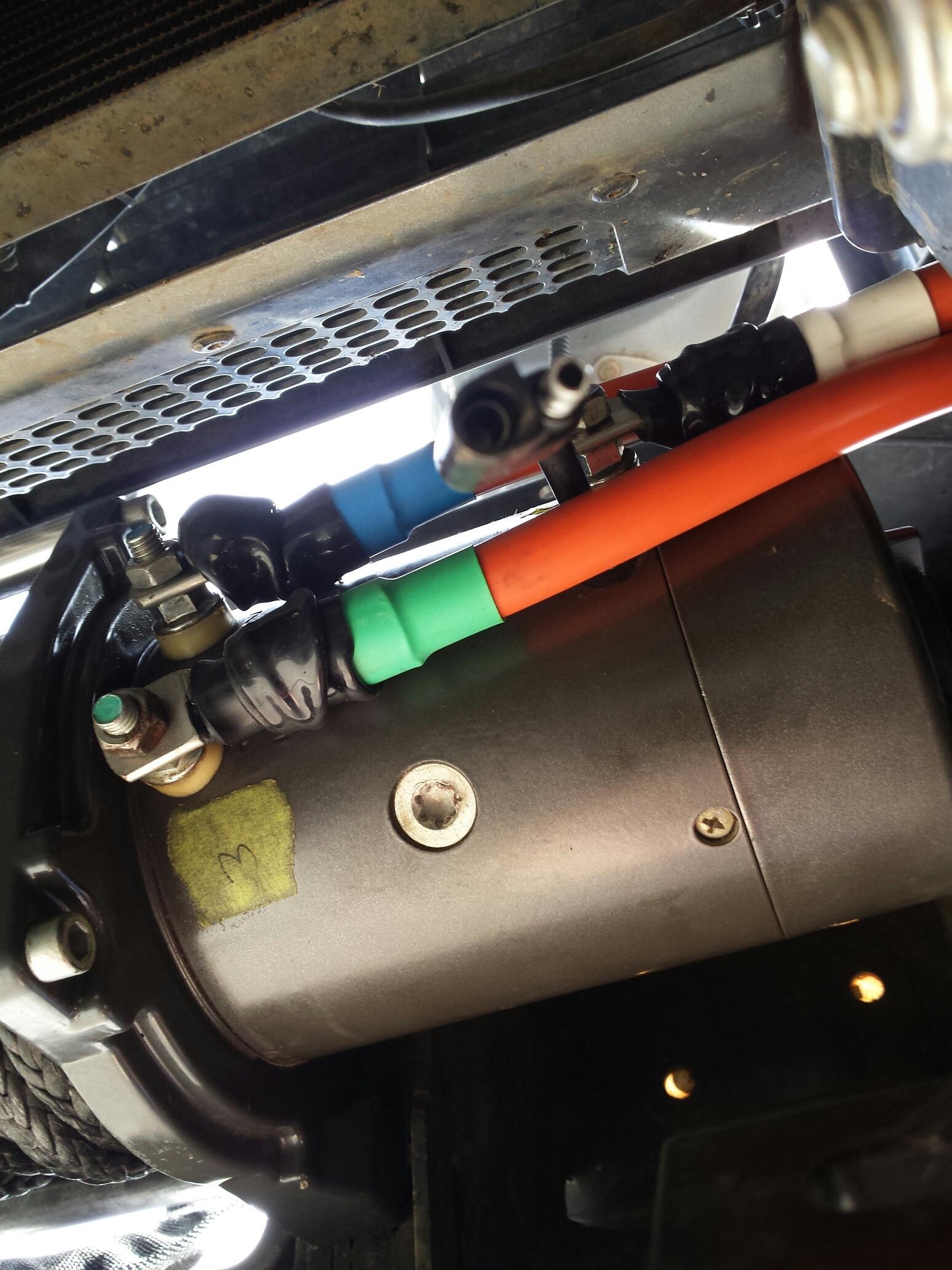
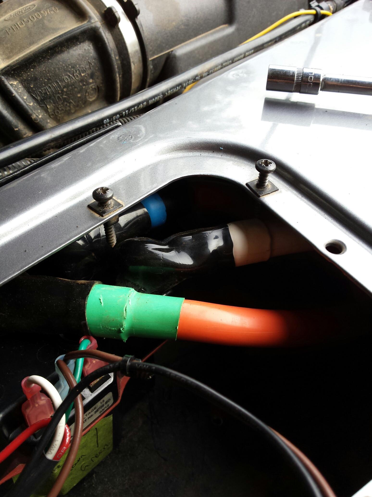
    I used 2 types of heat shrink - the black one is a extra thick heat shrink with a glue core, which is great for keeping the connection clean. From what I have researched, heavy cabling such as this is most likely to fail at a connection point, and this can be due to oxidation of the copper due to moisture ingress etc. For future proofing it, I used this, as well as a coloured tab which corresponds to the coloured Post markers which Warn uses on their winches (along with the F1 F2 and A markings).


    I used a MAPP gas torch to shrink the heavy tubing down. If you look closely, you can still see my finger print embedded into the molten plastic


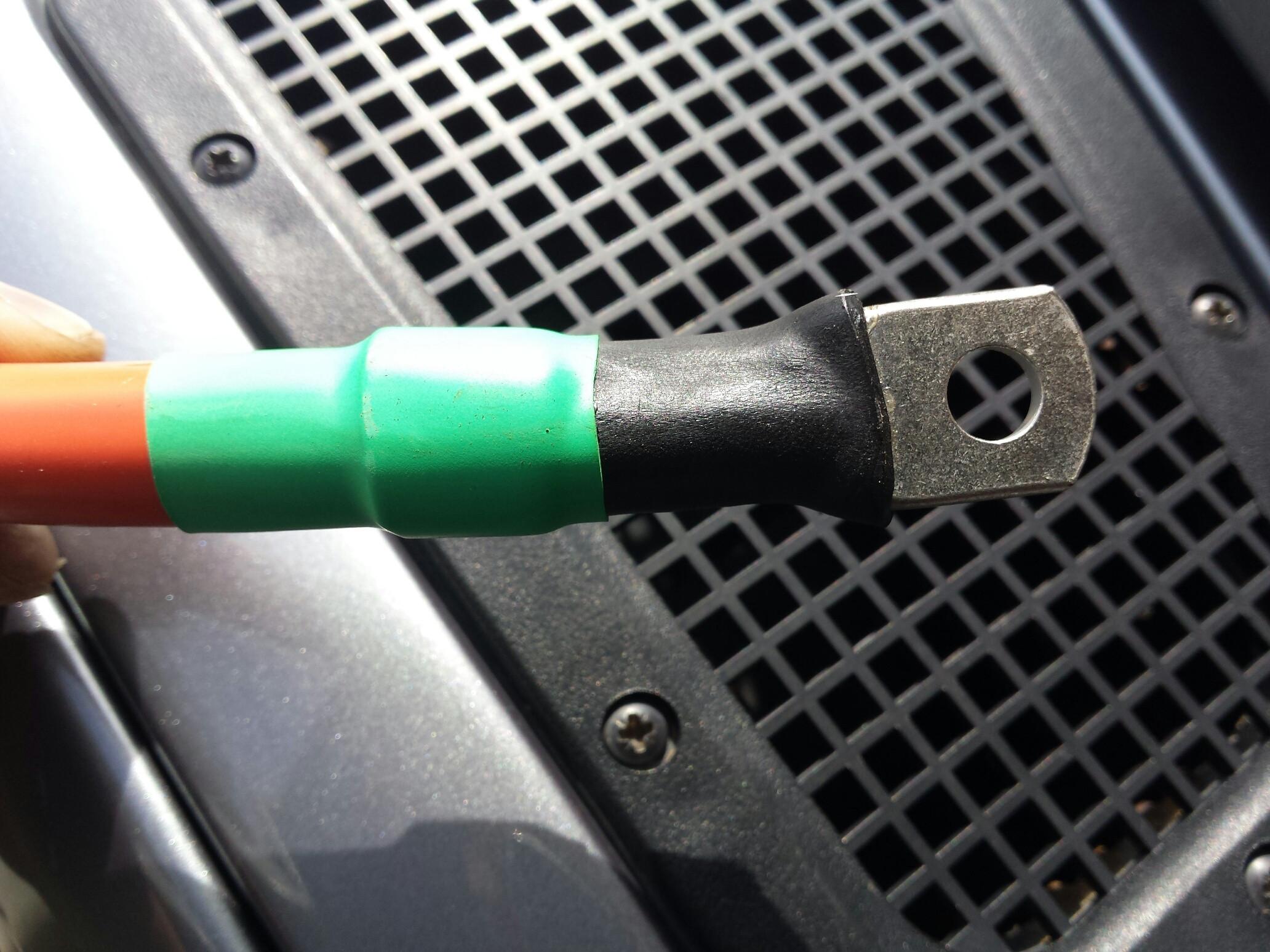
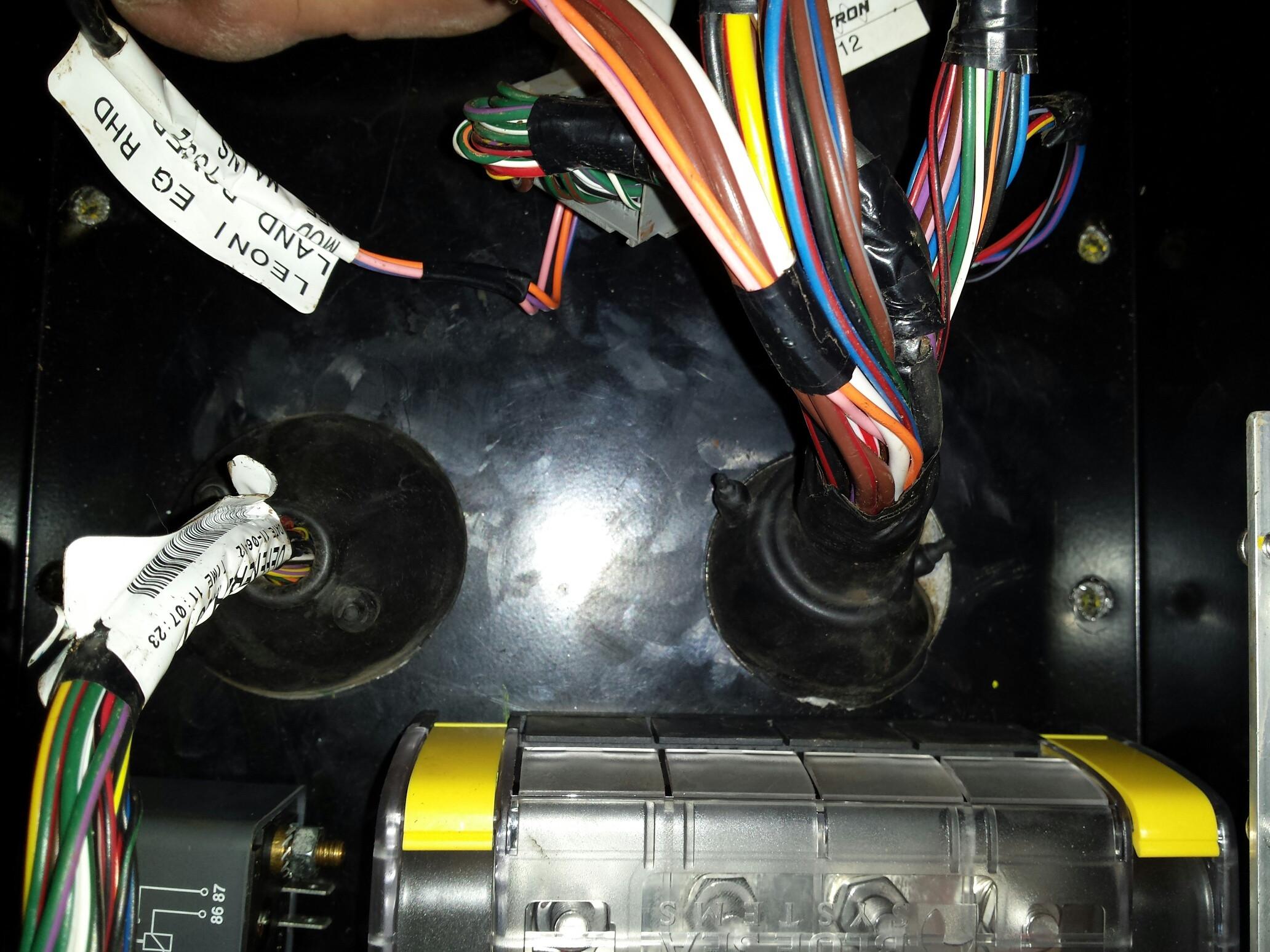
    All finished, with grommets installed before the lugs and heat shrink (pro tip!).


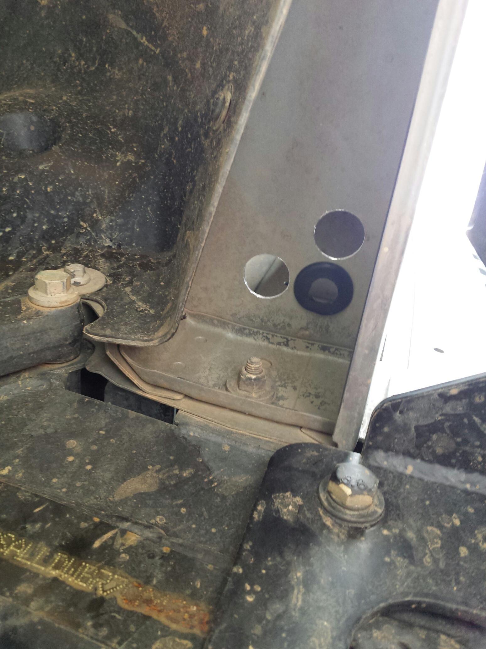
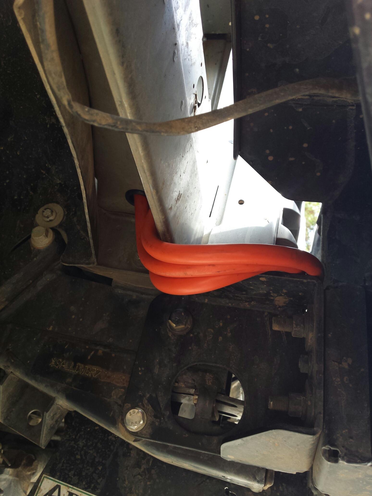
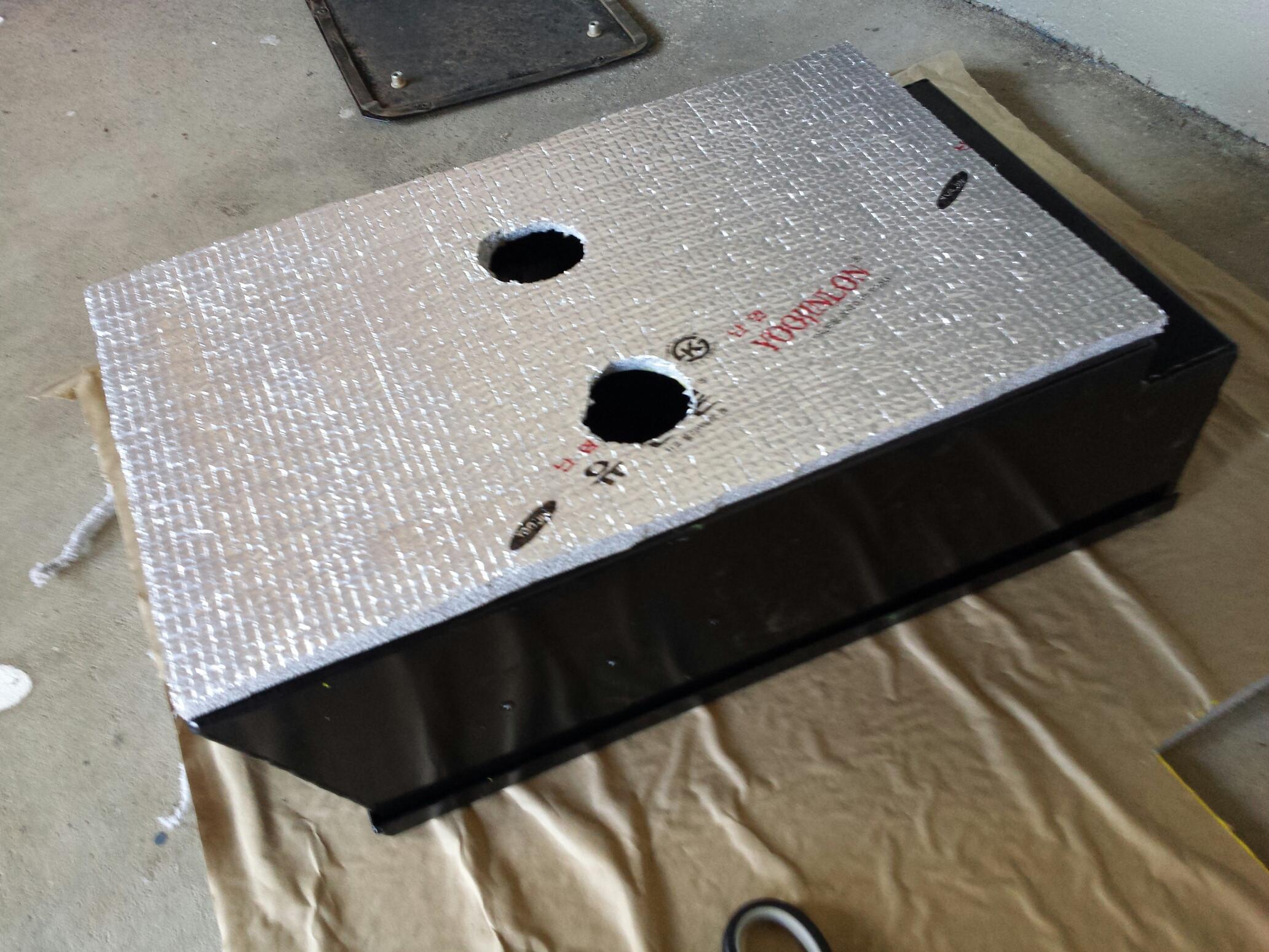
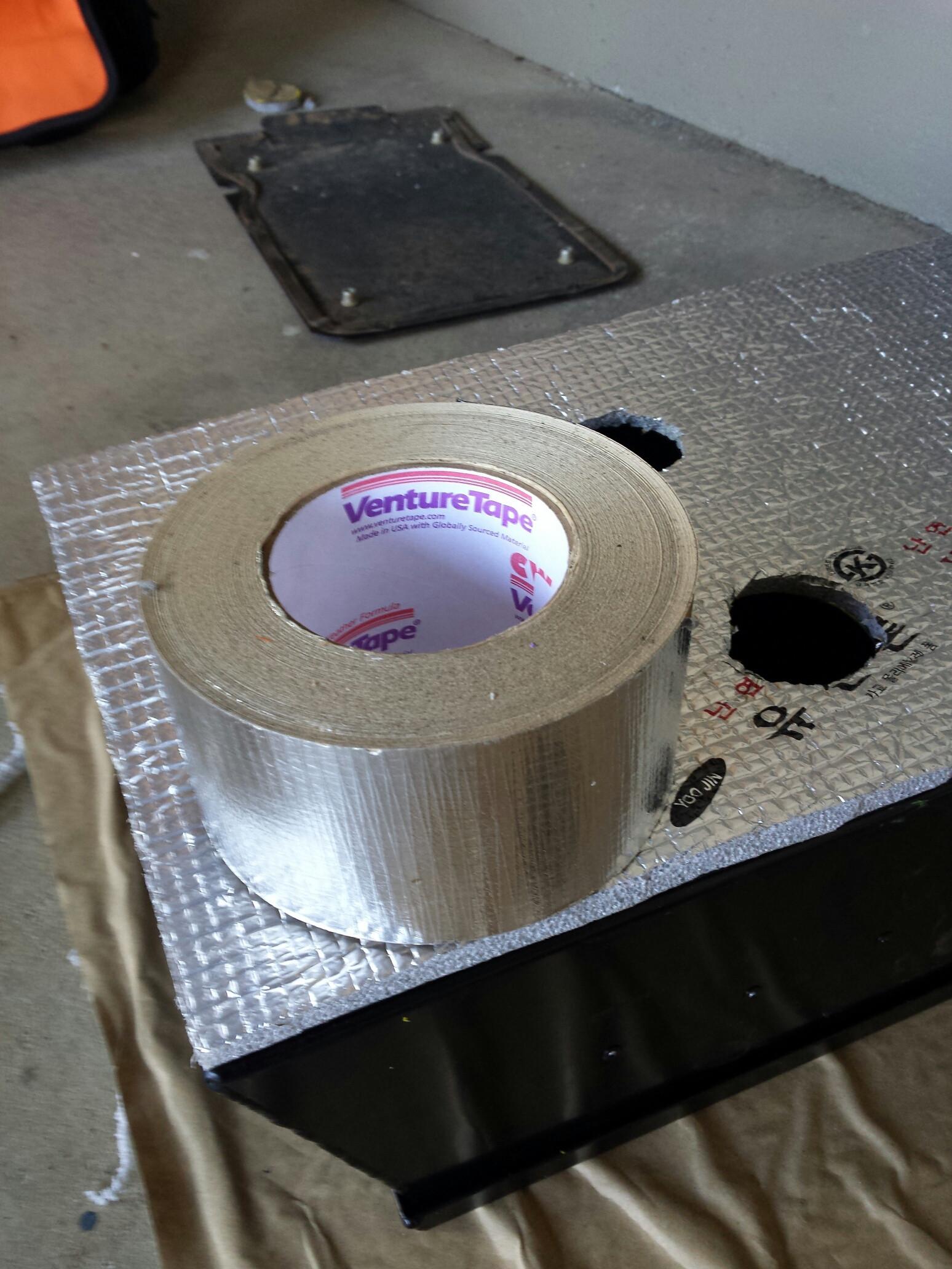
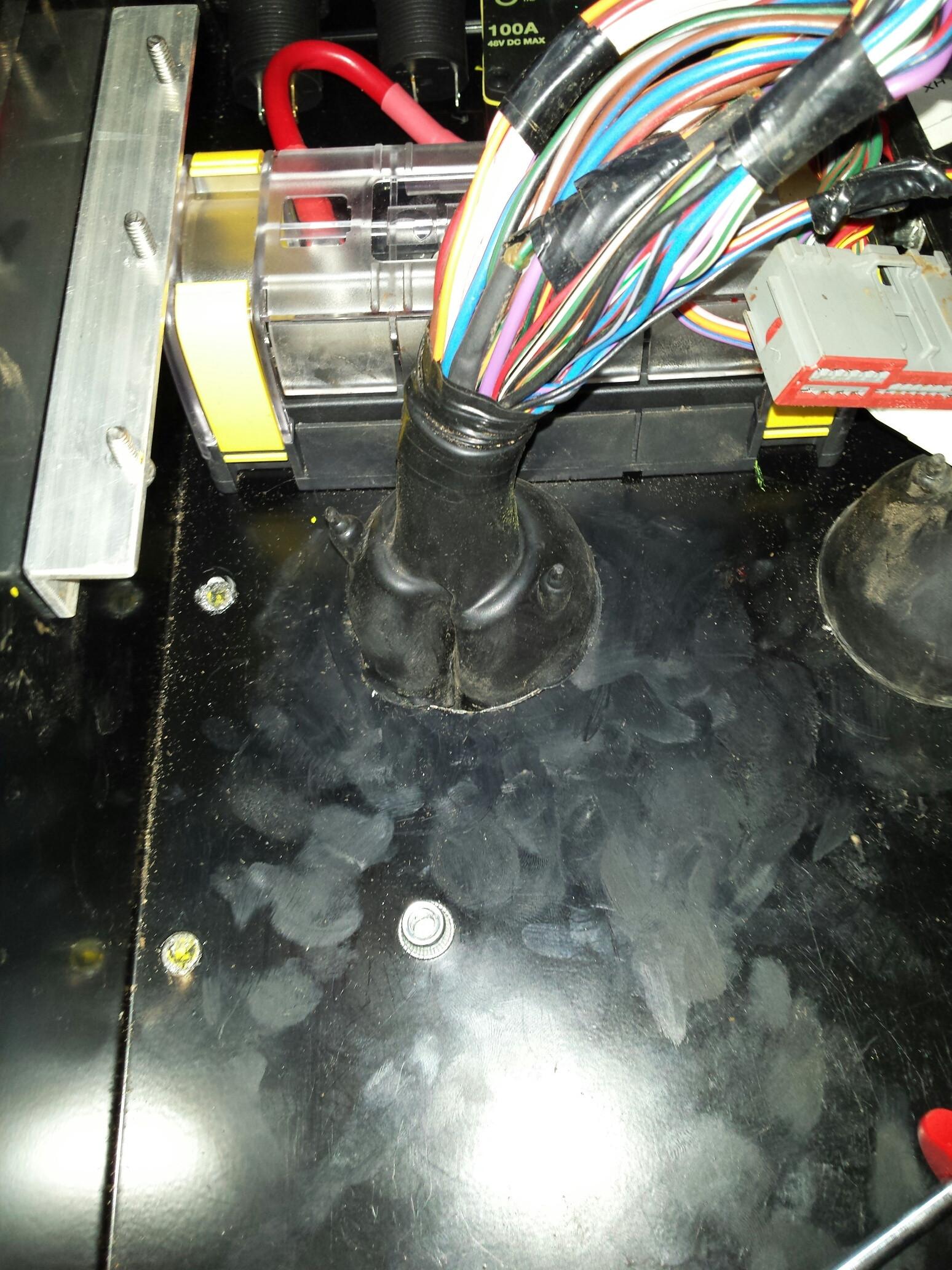
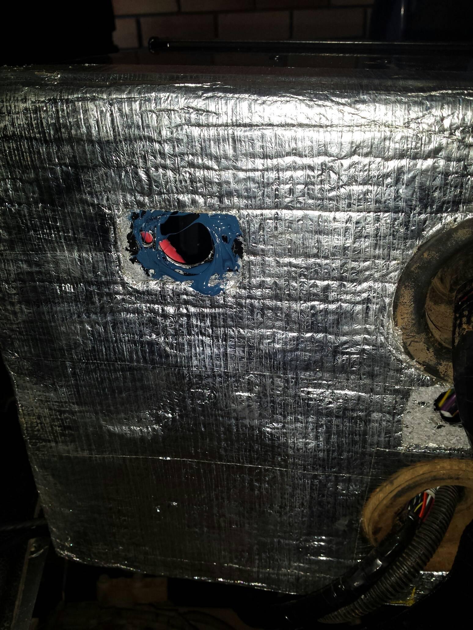
    The cables were routed from the winch terminals on the Drivers side of the winch, over the chassis rail / bullbar mounting point, and down to the panel which sits directly below the Driver's side headlight.
    I drilled 3x 25mm holes, and used 1 inch grommets


    I also used the supplied silicone boots for the cables I made up. If anything, this will keep the terminal posts that little bit more corrosion free. If I want to go full retard, I might even fill them with dielectric grease.


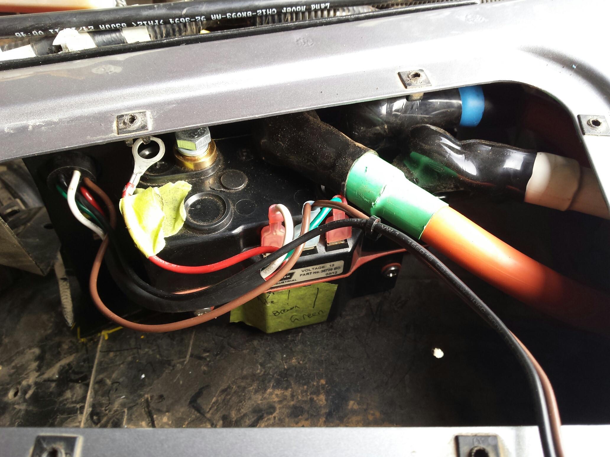
    With my bracket installed, it's all fairly compact in there.


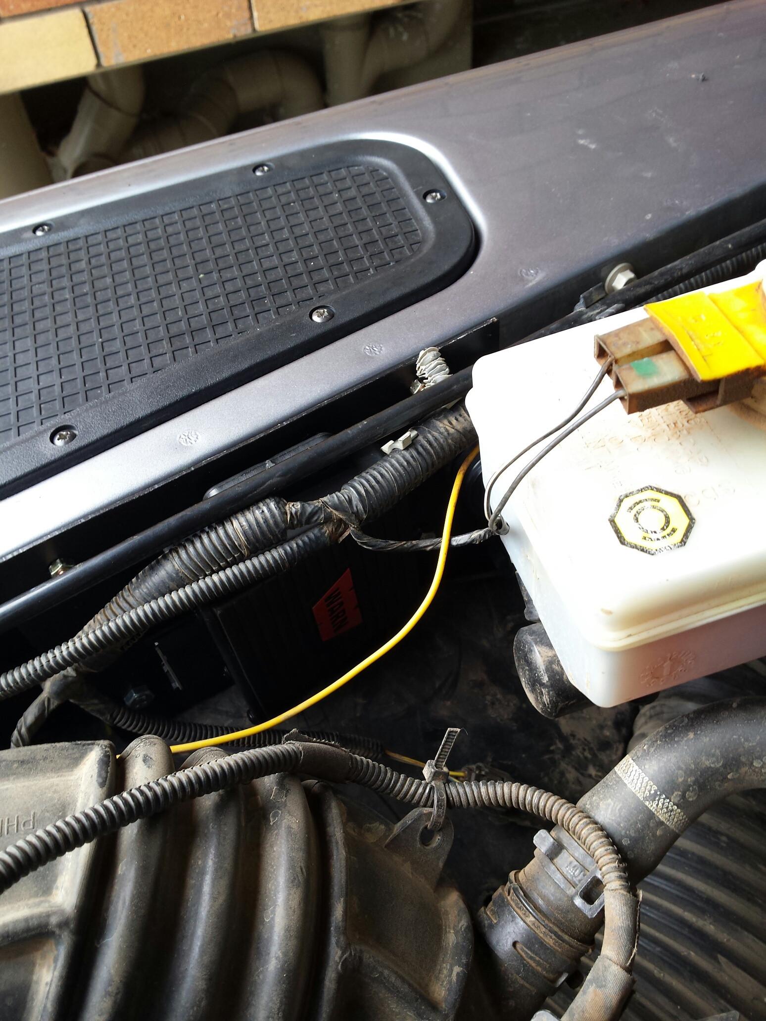
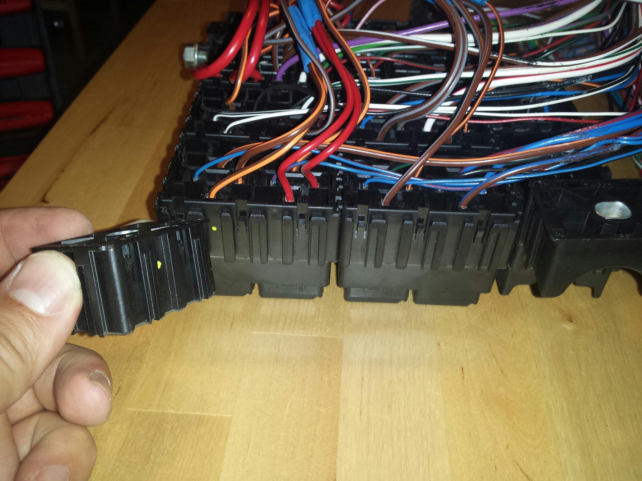
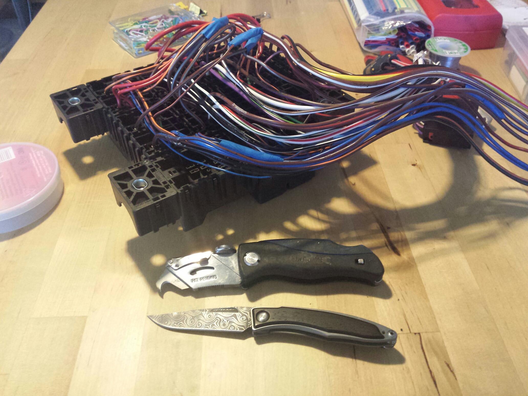
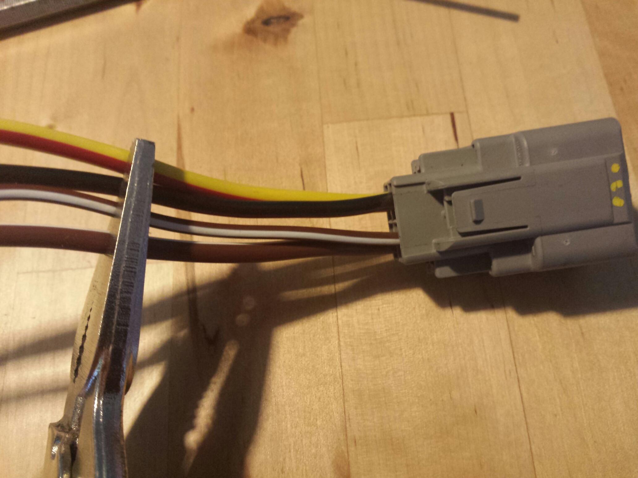
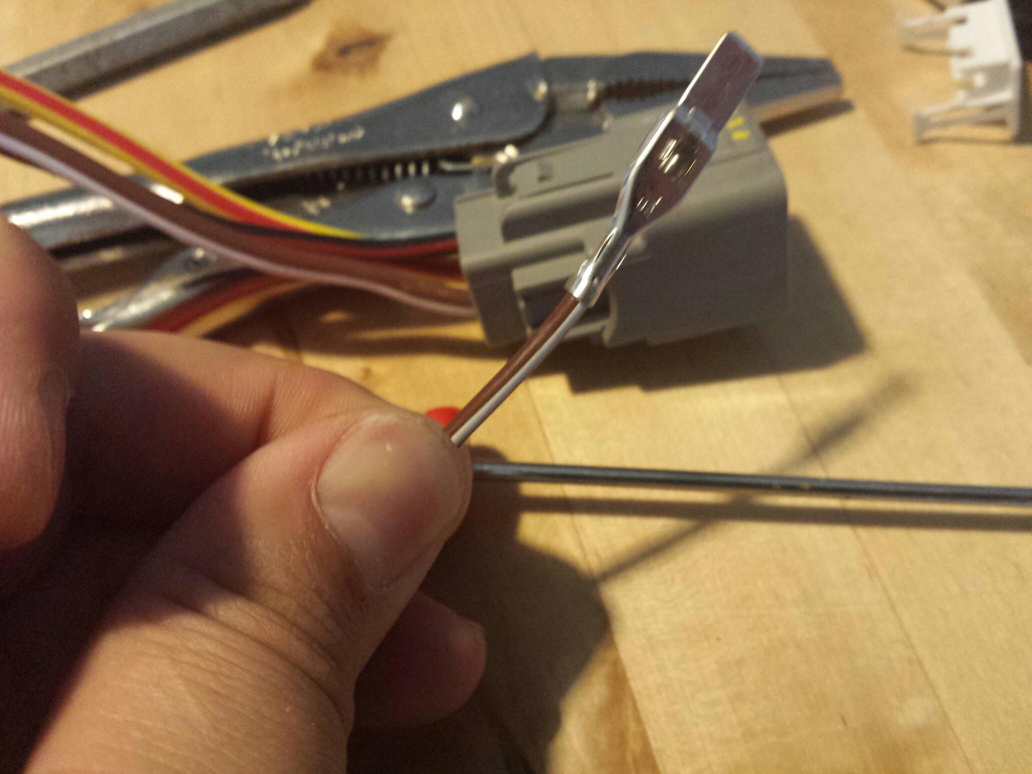
    The winch itself also has a black earth cable and a brown wire which need to be extended. I will cut the wires as shown (with a correct tool ) and they will follow the same route as the heavy cable.


    If you are playing along at home, the screws for the wing top cover will potentially wear thru the cables. I just cut mine down to length for good measure. I might look at some new screws when I can.


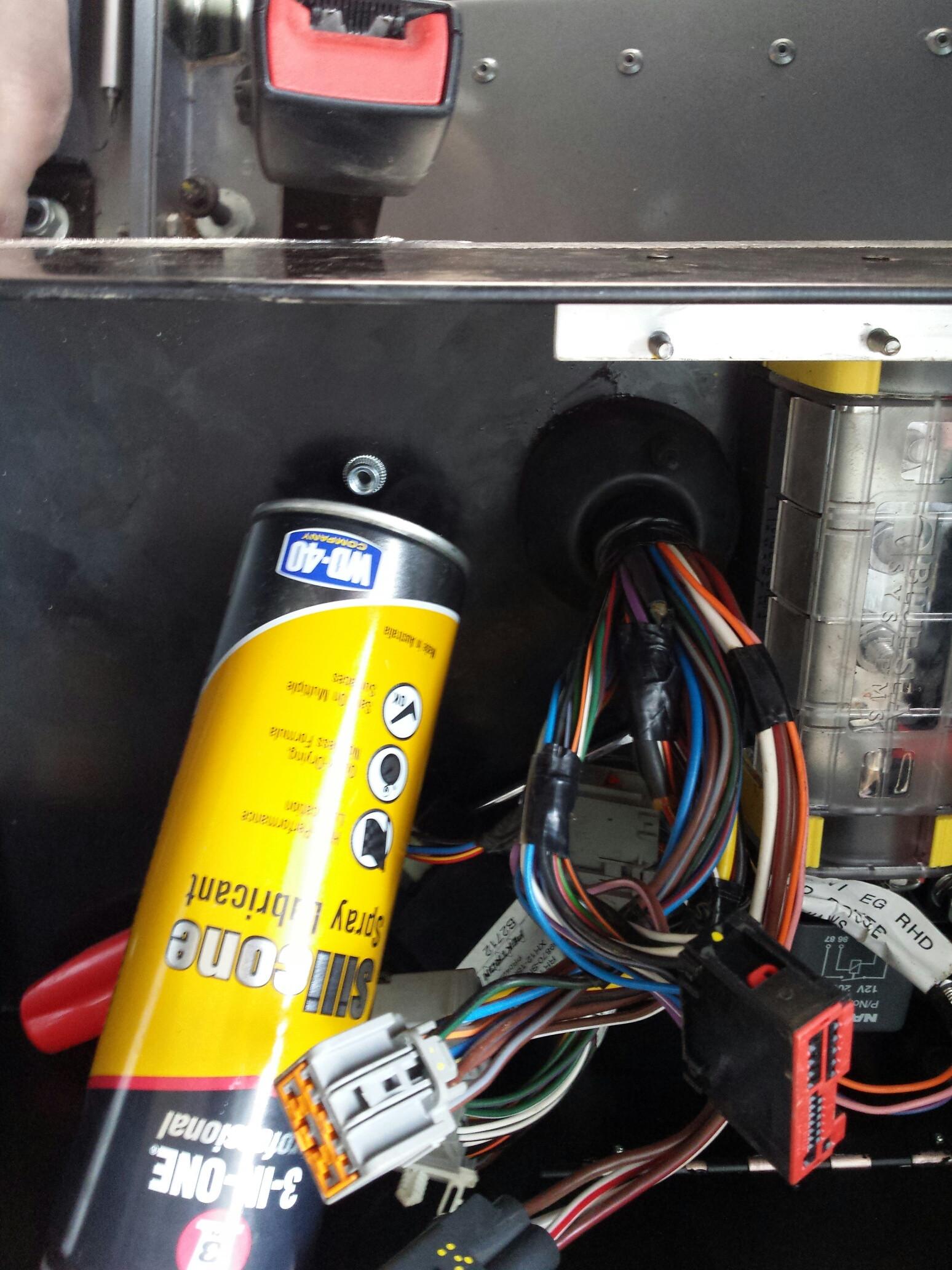
    From the engine bay looking in, it's a fairly sleek and stealthy install. should not get in the way of any mechanical work, and is still fiarly easy to access as long as you have a phillips head screwdriver and a 13mm wrench for the cable lug bolts.


    Next step is to plan the cable route and measure what lengths I'll need for the latter half of the cabling.
    The plan was to run 70mm2 cable from here back, which should give approx 0.6V voltage drop over a 6m span at 50 degrees C, and 360A draw. Warn recommends <1v drop for their winches, and 360A is the amperage draw for the full 9500lb pull on the first layer of the drum for my winch. Realistically, Its an ass-tonne of overkill, but it's a safety net should I need it (and a good way to spend a afternoon tinkering on the landy to boot!).
    -Mitch
    'El Burro' 2012 Defender 90.

  3. #33
    Tombie Guest
    Looks good...

    2 suggestions.

    Boots at winch motor - or a small impact can become a nice fire.

    Cover the cable where it exits the area beneath the light and turns over the metal.

  4. #34
    Join Date
    May 2014
    Location
    Tamworth NSW
    Posts
    4,295
    Total Downloaded
    0
    Quote Originally Posted by Tombie View Post
    Looks good...

    2 suggestions.

    Boots at winch motor - or a small impact can become a nice fire.

    Cover the cable where it exits the area beneath the light and turns over the metal.
    Thanks for the suggestions!

    I've got silicone boots on the cables at the winch motor, I just haven't stretched them over the posts in that pic.
    I've got a T-Type 400A fuse lined up to go on the positive cable close to the battery, and will also try to get an isolator switch in there somewhere - still undecided on what type of switch though, but have seen a suitable rotary switch option in the blue sea systems catalogue which sort of took my fancy.
    This should take care of the accidental short if it occurs.

    Not captured in the pics is the cable tying of the wire bundle, I've tied them up in a triangle shape, and there is clearance, but you make a valid point.
    Something like this should do the trick I'd think?

    Another option is some kind of spacer which can be mounted to the lip and clamp the cables down.
    I've seen options by swagelok, but not sure what they do for a 3-cable gang at the nominal 16.5mm cable OD I'm using.

    I've got my eyes on some of that poly cable wrap, but getting it to a diameter of a 50mm might be a challenge for the small length I'd require (approx 1m).
    They use it in hydraulics applications, so might go and see my friendly local hydraulics bloke and see what they have to offer.
    -Mitch
    'El Burro' 2012 Defender 90.

  5. #35
    numpty's Avatar
    numpty is offline TopicToaster Silver Subscriber
    Join Date
    Jan 1970
    Location
    Nundle
    Posts
    4,077
    Total Downloaded
    0
    Looking good Mitch.

    I'm in the process as you know, of rerouting all my auxiliary electrics and you seem to have all the right tools for the job
    Numpty

    Thomas - 1955 Series 1 107" Truck Cab
    Leon - 1957 Series 1 88" Soft Top
    Lewis - 1963 Series 11A ex Mil Gunbuggy
    Teddy5 - 2001 Ex Telstra Big Cab Td5
    ​Betsy - 1963 Series 11A ex Mil GS
    REMLR No 143

  6. #36
    Join Date
    May 2014
    Location
    Tamworth NSW
    Posts
    4,295
    Total Downloaded
    0
    Quote Originally Posted by numpty View Post
    Looking good Mitch.

    I'm in the process as you know, of rerouting all my auxiliary electrics and you seem to have all the right tools for the job
    You supply the shed space, and I'll bring the gear. My car port and living room table "workbench" can only hold so many projects at a time!
    I've got some gear left over too, which would help. I bought bulk packs of the coloured heat shrink, and I only used 30cm of the 1.5m long glue lined tubing. Can get a decent rate on welding cable thru work.
    Sing out when you want to have a crack at it
    -Mitch
    'El Burro' 2012 Defender 90.

  7. #37
    Join Date
    May 2014
    Location
    Tamworth NSW
    Posts
    4,295
    Total Downloaded
    0

    Lucas is an acronym for Loose Unsoldered Connections and Splices.

    Well bugger me.
    I'd heard about the (lack of) quality of the wiring in land rovers, but what I found today was worse than I expected:
    Tin foil crimps
    Electrical tape haphazardly bandied about said joins
    Shorts just waiting to happen.
    I've got better wiring in my 1980's vintage Datsun!

    Today I took the task of relocating the Puma's fuse block to the Ex Box. While the wiring leaves a little to be desired, I managed to tape it all nicely together, and re-route a few of the more oddball wires along a more direct route. A later project will be to take the fuse block back out and spend an evening in front of the TV soldering said joints together and applying heat shrink.

    Or maybe I could in vest in a jar of this:


    Before shot


    After


    As an aside, I think I've found a new favourite electrical tape. Picked up some 3M Super 33+ tape from Cetnaj. it's a vinyl tape, and IMO is way better than the Nitto stuff I usually get. It's thinner, more flexible, and stick like **** to a blanket - great for wrapping wiring looms!


    Ex Box insulation

    I took a page from Nugget's build thread and decided to insulate the bottom of the Ex box. Without this, I think it would be possible to have it double as a camp oven! Electrical resistance increases with temperature, and the circuit breakers I am using are rated to a temperature, so for the wiring's sake alone, this is best practice.

    I acquired an offcut of some closed cell PE foam matting with adhesive back and foil front (used in AC work).


    Sealed the edges with some foil tape


    ...This stuff is supposed to be a 'cold weather formula' so I did some testing to see if it was up to task.

    I took 2 pieces and subjected them to the most extreme environment I could think of (around the house):

    In the freezer on top of the ice cream for half an hour...


    In the oven at 150 degrees C for 15 minutes...


    After being subjected to these conditions, the tape was still tacky to the touch, was able to stick to itself, and still had good (albeit less) tensile strength. For my purposes, that is a win, bot for the tape, and the scientific method!


    ...So I used the foil tape to line the foam backing as well as seal the exposed foam edges of the ex box.


    Tool time!
    I don't know how I have survived without one of these for so long. Tensions and cuts to length with a few quick squeezes.


    Spiteful grommets are spiteful
    The Ex box holes are a snug fit for the grommets. I had the seats out and was standing over the box yanking and pulling to get it to seat, but it seems one grommet was too big for the hole (that's what she said).


    A wise man once said- "when in doubt, get the lube out".


    Crisis averted.


    Modifying fuel line brackets for securing ex box
    The fuel line brackets are 2 of the 4 mounting points for the ex box.
    In my case, the insulation requires a longer bolt than what is supplied in the bracket.
    In someone's wisdom, the bolt in the bracket seems to be riveted in, and cannot be removed.
    What I did was drill it out to 5mm, and replace the 5mm bolt with a longer, shinier 5mm bolt. +100 bling points.


    Going to weld the bolt head to the bracket tomorrow AM, and it should be as good (if not better) than new.
    Then it's a matter of bolting it in, and drilling the positive and negative thru holes for the power supply thru terminals, and make some cables up to the battery box proper.
    -Mitch
    'El Burro' 2012 Defender 90.

  8. #38
    Join Date
    May 2014
    Location
    Tamworth NSW
    Posts
    4,295
    Total Downloaded
    0
    And today's efforts was mainly tidying up the last tasks on the ex box, and re-fitting the interior.

    Some pics of the 99% finished project:

    Cut a hole in the insulation for installation of the thru terminals for power and earth. Used some gasket goo to seal it all up.


    In Situ


    For now I've just bundled the cables and connectors under the fuse block flap. I'll probably end up re-jigging it a bit so that the connectors line up along the rear or driver's side of the ex box. The lay of the wire as it stands is down the passenger side, which I will need to re-route.


    Having some method of attaching the connectors to a rail using their factory grooves would be ideal... just not sure where I could find such a beast. LR use a slide on style clip which has a press fit 'christmas tree' style fastener, but I want to avoid any more holes in the ex box if at all possible.


    I put some of the foam matting down below the fuse block, so that any wires do not abrade on any grit which accumulates, or any steel surfaces. It's not stuck down, so this may or may not be a permanent addition. We'll see what I can manage with the wiring loom as it is.


    I even stuck the fuse block sticker on the lid of the ex box. Bonus points!


    -Mitch
    'El Burro' 2012 Defender 90.

  9. #39
    Tombie Guest
    Looking good

  10. #40
    Join Date
    May 2014
    Location
    Tamworth NSW
    Posts
    4,295
    Total Downloaded
    0

    Spaghetti Western

    Today I tackled the wiring and fuse board in the puma.

    Initially, I just taped up the wiring loom as per the Mulgo instructions, but I was left with a dog's breakfast of harness connectors, and wiring all over the place. I'm hoping to get this part of the install tidied up as much as possible. The plan was to move the loom from the natural fall of it from the passenger side, to the driver's side of the fuse box, allowing a better wire path.

    The way I worked it out, is there would be 2 ways to go...
    1) Totally rearrange the modular design of the fuse block to make it fit the application, or,
    2) Work with the form factor provided, but change the wiring path to be more compact.

    The fuse board in the 2012 puma is a modular clip together design, as seen below:


    so with some patience and tomfoolery, it would be possible to completely unclip the fuse board into its sub sections and make it work, but at this juncture, It's a mammoth task, would require custom brackets and need the fuse / circuit drawing to be revised. Plus I'm red/green colourblind, so bugger that

    First step was to remove all the electrical tape off the wiring underneath.
    Tools of choice were a hook blade on a box cutter, and a nice sharp Chris Reeve folder. A gentleman is only as sharp as his knife...


    The fuse block is setup with a main power feed on the side using a M8 stud and a 13mm nut. From here, we have the fusible links, and bridge wires to the individual circuits / relays. Point is, I needed to separate the wires belonging to connectors with the wires bridging circuits in the board, while trying to optimize the wire path (both for future plug location, and not stretching / straining and wires).

    When I removed the block from its original location, I arbitrarily labelled the connectors with dots to tell them apart easier. This plug has 4 wires, one of which I needed to re-route thru the spaghetti maze to allow the connector to move to the opposite side of the loom:


    Once you remove the plastic retainer inside the connector, use a scribe pick or small screwdriver to release the clip which holds the spade terminal in. I use one hand to apply gentle tension on the wire, while picking the clip. You will end up with this:


    Thread the wire that you have released from the bundle thru the fuse block wiring to where it needs to be, and reconnect.
    I only undo one wire at a time, so that there is no confusion when it comes to reassembly. This would be a bad news scenario if you screwed that up


    After some time, you'll end up with something like this:


    The connectors have a T-slot style groove on them, which works with the modular style fuse block (to some degree).

    For one connector (the 4 wire black connector with the waterproof seal in it), I made up a J shape clip using some 1mm aluminium to hold it in securely to the side of the fuse block.


    I did some tape work underneath to bundle cables belonging to the same connector, and help 'train' their path. I'm lucky that the vehicle is still relatively new, and the wires and connectors are not brittle:


    I'm seeking thoughts on this though... The factory location used a raised platform to allow airflow around the wiring below the fuse block. Now that things are much more compact, is it possible that wiring could get too hot? I'm also taking a gamble on the taping of wires... not sure if there will be any kind of interference between wires in close proximity (inductance effect?).
    If you have any thoughts, please post below!

    Driver's side view


    Front view:


    Looking from the rear:


    As far as the ****ty crimp joins in the wiring, I let that sleeping dog lie...
    The ones I inspected were solid, and looking past the dodgy electrical tape insulation job, it was a good electrical connection. It could be debated that my soldering would not do it justice


    On a completely unrelated note, I installed some rubber edge strip on the front winch wiring as per Tombie's recommendation. That side of it is pretty much sorted now.


    Well that's about all for now...

    Until next time,
    Cheerio.
    -Mitch
    'El Burro' 2012 Defender 90.

Page 4 of 69 FirstFirst ... 234561454 ... LastLast

Bookmarks

Bookmarks

Posting Permissions

  • You may not post new threads
  • You may not post replies
  • You may not post attachments
  • You may not edit your posts
  •  
Search AULRO.com ONLY!
Search All the Web!