


 Reply With Quote
did the site have a graph for the V8?

 YarnMaster
Subscriber
YarnMaster
SubscriberHi Guys;
This is more of an information brief I found on the web and wasn't sure where it should be posted up with regards to a TD5 engine , but it may/maynot make interest read for some of you TD5 owners.
tech - Td5 diesel engine
Contents
* Introduction
* Engine specification figures
* Engine construction
o Cylinder block
o Fracture split con-rods
o Flywheel
o Cylinder head
* Fuel supply system
* Oil pump
* Electronic unit injector (EUI)
* Oil filter
* Turbocharger
* Cooling system
* Auxiliary drive belt
* Crankcase ventilation
Key features of the engine include:
* Five cylinder engine configuration
* Cast iron block with aluminium cylinder head and structural aluminium
engine sump
* Overhead camshaft with a single rocker shaft
* Hydraulic lash adjusters with independent finger followers
* Electronic unit injectors
* Timing chain and chain-driven oil pump
* An aluminium lower ladder frame, incorporating the oil pump
* Centrifugal oil filter
* Fuel cooler
* Integrated oil cooler
* A new engine management system
* Sequential cyclone engine breathing system
* An integrated vacuum pump with the alternator
Engine specification figures
* Cubic capacity 2498cc
* Piston stroke 88.95mm
* Piston bore 84.45mm
* Compression ratio 19.5:1 � 0.5
* Maximum Governed rev/min. 4850
* Maximum rev/min (e.g. overrun) 5460
* Target idle speed >0�C 740 rev/min.
* Target idle speed <0�C 1000 rev/min.
* Maximum torque (manual gearbox fitted) 300 Nm
* Maximum torque (automatic gearbox fitted) 315 Nm
* Maximum power New Discovery 101.5 kW @ 4,200 rev/min
Defender 1999 MY 90.0kW @ 4,200 rev/min
Engine construction
The engine is an in-line five cylinder, turbocharged direct injection compression ignition unit. The block is
of cast iron construction with an aluminium cylinder head. The engine uses �through bolt� technology. This
provides excellent structural support and rigidity. An aluminium ladder frame secures to the bottom of the cylinder
block to enhance the lower block rigidity. The ladder frame also incorporates a rotary oil pump. This oil pump passes
pressurised oil through the aluminium ladder frame into the cylinder block. A gasket seals the ladder frame oil gallery
and the cylinder block oil gallery. This gasket must be replaced whenever the ladder frame is removed.
Cylinder block
The cylinder block incorporates oil squirt jets which are used to cool the pistons. Each squirt jet incorporates a
pressure valve which shuts off whenever the oil pressure falls below 1.5 Bar. The engine does not feature a
conventional adaptor plate, instead, the gearbox bolts directly to the engine block. The gearbox casing itself
houses the starter motor and provides access for the TDC positioning tool, which engages directly into the flywheel.
The engine has an aluminium structural sump sealed to the cylinder block with a rubber gasket. This gasket features
integrated metal sleeves (compression limiters) at the points where the sump bolts pass through the gasket. This
prevents the gasket from distorting as the sump bolts are tightened. The sump gasket should be fitted dry to cleaned
and dry surfaces. The crankshaft is constructed of iron and incorporates journals with rolled fillet radii to increase
the crankshaft�s ability to withstand �bending� fatigue. It is not possible to regrind the crankshaft, due to its
design and the techniques used in its construction. The crankshaft main bearings feature a grooved shell, which locates
in the cylinder block and with a smooth shell in the cap. The number 3 main bearing includes provision for the two thrust
washers; these washers are only available in a standard size. It should be noted that all the main bearing caps have a
slight interference-fit with the cylinder block. This feature negates the need for main bearing locating dowels.
The pistons feature a graphite coated skirt and incorporate an integral combustion chamber. The pistons have three
piston ring grooves, housing two compression rings and one oil-control ring. An internal oil gallery, fed by the
oil squirt jet, cools the piston. The piston design eliminates the need for additional strengthening rings using
its shape to transfer the combustion forces through to the con-rod.
Fracture split con-rods
The con-rod is identical in design to the con-rod fitted to the Freelander L series engine. It is a fracture split
con-rod. This means that the big end bearing cap has no machined surface in contact with the con-rod. In manufacture,
the con-rod is bored to a nominal diameter as a one- piece unit. Two grooves are then machined into the inner land and
then the cap is forced apart. This causes the metal to fracture, leaving a unique mating surface. Once this process is
completed, the cap is refitted and tightened using two retaining bolts and the final internal diameter is machined.
Utilising the fractured state of the cap ensures that the two pieces of the con-rod fit perfectly and possess a strong
resistance to lateral movement (sideways movement).
The bolts are located off-centre. This serves to ensure that the cap is fitted to the rod in the correct orientation.
If, when the con-rod is out of the engine, the cap is fitted incorrectly (the wrong way round) and the bolts are tightened
then the con-rod must be replaced. This is necessary because the unique profile of the mating surfaces will have been
damaged when the cap was tightened. The cap will no longer locate correctly, even if it is turned back to the correct
position.
The small end of the con-rod is machined to a taper. This allows for clearance between the piston head and the con-rod
and provides increased load capability by increasing the surface area on both load sides of the gudgeon pin. The small
end is lubricated by a splash-feed, facilitated by the squirt jets. The big end bearings have no featherway to locate
them laterally. They rely solely on �bearing nip� to control their position and to eliminate rotational and lateral
movement. The bearing shell located in the con-rod is different to the bearing shell fitted in the con-rod cap. The
con-rod bearing goes through a manufacturing process called �sputtering�. This process is used to form very pure
materials. In this case, the sputtering process is used to increase the con-rod bearing shell resistance to wear and
is used to offset the greater wearing loads experienced by the top bearing shell. The sputter bearing can be identified
by having a shiny surface (bearing shell to con-rod side), a dedicated part number and a different appearance when
viewed from the working side of the bearing as compared to the back of the bearing.
Flywheel
The flywheel is a �dual-mass� flywheel. This means it has a proportion of its mass mounted by an internal spring.
A dual-mass flywheel helps to dampen the unavoidable variations in crankshaft rotational speed which occur at the point
of combustion for each cylinder. This damping action helps to reduce drive train vibration particularly when the engine
is at low speed and at idle. The flywheel also incorporates a series of holes drilled into the circumference. These holes
work in conjunction with the crankshaft sensor to feed back information on the crankshaft speed and the crankshaft phase.
There are 31 drilled holes, spaced at 10� intervals, around the flywheel. At five 10� intervals the crankshaft has
not been drilled. This acts in the same manner as having a �missing pole� (i.e. as used on the V8 engine fitted to
the Range Rover pre-1999 MY). The missing holes are placed unevenly around the circumference of the flywheel. By having
the crankshaft drilled in a unique sequence, the ECM is able to determine its position in the engine�s cycle within a
maximum of 130� of crankshaft rotation.
Cylinder head
The cylinder head face is heat treated to increase its durability, so it cannot be re-faced. The head houses four glow
plugs (number 5 cylinder does not have one) and two valves per cylinder. It also features the machining for the camshaft,
hydraulic lash adjusters, the electronic unit injectors and the low pressure fuel rail.
The camshaft locates between the head and the cam carrier. These two components are line bored, so form a matched pair.
It is important to note that the head is subjected to a force equivalent to that of clamping the cylinder head to the
surface block when it is line bored. This ensures that the camshaft bearing surfaces match the profile of the camshaft
journals perfectly when the engine is in an operating condition. If the need arises to replace the cylinder head or the
cam carrier, the other component must also be replaced. The cam carrier is sealed to the cylinder head by liquid sealer,
in this case Hydrogrip 2000. It is important to apply the correct amount of sealer. Always follow the procedure detailed
in the workshop manual to ensure that the correct amount of sealer is applied.
The rocker shaft sits above the camshaft in the cam carrier and has on it five rockers. These rockers are used to generate
fuel pressure inside the EUI injectors.
The valves use finger followers to transfer the camshaft lobe movement into vertical valve movement. The finger followers
locate over the hydraulic lash adjusters and the tops of the valves (see figure below). The finger followers are not held
rigidly into position, they hold their position by locating on top of the valve and locating over the hydraulic lash
adjusters pivoting ball. The valve is activated by the lobe of the camshaft pressing down on the roller of the finger
follower.
Finger follower and lash adjuster
When the hydraulic lash adjusters are removed from the engine, they must be stored upright and in clean conditions.
Failure to follow this procedure can result in serious engine damage when they are reinstalled.
The cylinder head incorporates the fuel gallery, as previously mentioned. Supply and return connections are located
at the rear of the cylinder head. All the fuel pipes are connected by means of quick-fit connectors. A fuel cooler
is mounted on the side of the inlet manifold (see figure below). The fuel cooler cools the hot fuel from the cylinder
head before it returns to the fuel filter. The fuel cooler has two coolant connections to the radiator. The radiator
incorporates a small diameter tube dedicated to supplying coolant for the fuel cooler. The small diameter of the tube
slows the coolant flow, which �super cools� the coolant before it is supplied to the fuel cooler. The fuel cooler
has a thermostat which opens when the coolant inside the fuel cooler reaches approximately 70�C (160 �F). It is
important to cool the fuel returning to the fuel filter, as this ensures that the fuel within the fuel circuit is kept
at a predetermined temperature for optimum performance and emissions.
Td5, unlike previous engines, is equipped with a fuel cooler on the fuel return lineFuel supply system,the fuel supply system on New Discovery diesel derivative uses an electric two-stage pump. The pump is submerged in
the fuel tank. Fuel passes through the pump twice before it flows to the engine. In the first stage, the fuel is drawn
from the swirl pot and flows out of the fuel tank to the fuel filter (line A). The fuel filter is located on the outside
of the chassis on the right hand side of the vehicle, forward of the rear wheel. This fuel filter is of a canister design
and should be replaced at scheduled intervals, according to the service maintenance service sheet. Once the fuel has passed through the filter, it returns to the fuel tank (linewhere it enters the fuel pump for the second time. The fuel pump then boosts the pressure to 4.0 Bar. The boosted fuel pressure is controlled by a pressure relief valve located in the aluminium fuel connector block, which is situated on the rear of the cylinder head. The pressure relief valve controls the fuel pressure by regulating the amount of fuel returning to the fuel filter. The fuel connector block also retains an additional �fit for life� fuel filter. This filter should not be replaced under normal circumstances. However, if a blockage does occur, then the housing can be removed and the filter replaced.
It is extremely important that no dirt enters the fuel rail as this could lead to engine misfire by blocking an injector
or making it stick open. It can also lead to combustion gases mixing with the fuel in the fuel rail, causing the engine
to stop running.
The fuel is supplied to the engine (line C) and into the gallery within the cylinder head. The injectors then use a
proportion of the fuel. The return pipe allows the excess fuel from the head (line D) to flow into the fuel cooler.
Finally, fuel flows to the fuel filter (line E) and back into the fuel pump, ready for the next cycle.
Care should be taken when disconnecting any part of the fuel system as it can contain hot pressurised fuel. In cases
where an EUI needs to be removed, follow the procedure detailed in the workshop manual. Failure to disassemble the engine
correctly, or to not take heed of the warning associated with allowing fuel to drain into the combustion chambers, can
lead to engine damage.
Fuel flow diagram
A. LP out
B. LP in
C. HP out
D. Return pipe
E. Spill return
F. Filters
G. Fuel cooler
H. HP stage
J. Water jacket
K. Air bleed
L. LP stage
M. Electonic unit injectors
N. Water out
O. Hot fuel in
P. Cool fuel out
Q. Cool water in
Oil pump
The oil pump, as previously mentioned, is located in the stiffener plate. A chain drives it from the crankshaft. The oil
pump contains no serviceable parts except for the pressure relief valve spring. The free length measurement of this spring
is detailed in the workshop manual. It is the free length of the oil pressure spring which determines whether the pump is
suitable for refitting into the engine. Before the oil pump or crankshaft drive sprocket can be removed, the oil pump drive
sprocket must first be removed.
Electronic unit injector (EUI)
The injectors used by the Td5 engine are located in the cylinder head. A copper washer and an �O� ring are used to seal
the injector nozzle and injector body to the cylinder head. If, at any time, an injector is removed then this washer and
the injector �O� ring must be replaced. Extreme care must be taken when removing an injector from the cylinder head as
the tip of the injector can be damaged if it is handled incorrectly. If the copper washer fails to seal the injector to
the cylinder head, combustion gases will contaminate the fuel in the fuel gallery. This results in the fuel becoming
aerated. If this happens, the engine will suffer poor starting and poor performance. Even with relatively small amounts
of combustion gas in the fuel, the engine performance will suffer noticeably. The injectors �O� ring prevents the
fuel in the fuel gallery from entering the engine oil supply.
The EUI injectors are very susceptible to foreign matter in the fuel rail or any dirt or particles around or in injector
body between the �O� ring and the copper washer. No attempt to clean this part of the injector should be made. Always
follow the procedure detailed in the workshop manual when removing the EUI injectors.
The EUI injectors are manufactured by Lucas
The injectors are electronically operated units in which the fuel injected is pressurised mechanically. Each EUI consists
of a hydraulic plunger, a conventional injector nozzle and an electric solenoid. The hydraulic plunger is driven
mechanically
by the camshaft and rocker assembly. The injector operates in four stages:
1. The camshaft lobe turns and transfers mechanical force and motion to the rocker, which is in contact with the
injector hydraulic plunger. This transfer of mechanical force starts to move the plunger down inside the injector.
At this point, the injector has fuel flowing through it because of the action of the pump located in the fuel tank.
N.B. Fuel exits the injector via the spill hole back into the fuel rail
2. As the plunger travels down, it closes the inlet port and prevents more fuel entering the injector. The fuel
already in the injector can still exit the injector at this stage because the EUI solenoid has not shut off the spill
port
3. At a calculated time, the ECM will supply a voltage to the injector solenoid, causing it to activate. This will
close the injector spill port and cause the pressure within the injector to rise very rapidly. At this point, the injector
will spray fuel into the combustion chamber at very high pressure (up to 1500 Bar. As a comparison, the current 300 Tdi
engine injects fuel at approximately 600 Bar)
4. At the calculated time, the ECM will remove the voltage to the EUI injector solenoid. By doing so, the spill port
will open and fuel will now flow through the injector, rather than out through the nozzle. The hydraulic plunger will
return to its rest position by means of a powerful spring. The EUI is now ready for the next injection sequence
It is critical that each injector delivers the desired quantity of fuel at the required time. To do this, its opening
and closing times must be controlled precisely. Despite the fact that the injectors are manufactured to extremely close
tolerances, an amount of variation may exist between them. This is due to slight differences in spring tension and nozzle
bore dimensions. As a result of this variation, the ECM must be informed of the precise specification of each injector.
This enables the ECM to adjust its opening and closing injection points to gain the maximum fuel efficiency. This
procedure is called the calibration process.
On top of the injector there is a five letter code. This code is used in the EUI calibration process. It details the
exact performance or �profile� of the injector. Each injector is tested after manufacture and is measured against
a nominal start of injection point, end of injection point and an idle quality factor. The graph below demonstrates
how this alpha code is used to tighten the tolerance of the EUI.
The EUI alpha code can be used to tighten the EUI tolerance in the ECU
The first two letters of the alpha code refer to the degree of variance from a nominal injector to the measured injectors
start point. The second two letters in the alpha code refer to the end of the injectors tolerance. The tolerance band for
the start and end of injection is � 127mS (0.000127 seconds). The last letter in the alpha code is a measured variance
in idle performance. The injector is given one of three idle letters: A, B or C.
The alpha codes used for both the start point and the end point are not sequential, i.e. not AA through to ZZ. The codes
have been picked at random to stop the possibility of deliberately over-fuelling the engine in the search for greater
performance.
The letters do not denote that one injector is better than another injector. The letters give the ECM the mapping
adjustment needed for that particular injector, to enable very precise fuelling and smooth idle performance.
It is important that the injector code is programmed into the ECM if an injector is replaced, or if the order of the
injectors is mixed up. This procedure is completed with the aid of TestBook. The injectors are operated electrically
by the ECM, which is able to produce a voltage of approximately 80 volts at 8 amps to shut the injector spill port.
This is a considerable amount of electrical energy. Appropriate care should be taken while working with a running engine.
The rockers which transfer the downward force on the EUI must be adjusted correctly at all times. The process used to
set the adjustment is dissimilar to conventional tappet adjustment procedures. The procedure is as follows:
1. Loosen the lock nuts on all the adjusting screws (this should have been completed before the rocker shaft was
removed)
2. Set the engine to a position where the EUI to be adjusted is fully compressed, i.e. the cam lobe is at its highest
point. There is a timing mark on the front of the camshaft for each of the injector�s lobes. This mark will align with
the edge of the cam carrier housing to signify that the relevant injector lobe is at its maximum point
3. Screw the adjuster �in� to further compress the EUI hydraulic plunger spring (this will feel quite stiff).
Stop when the plunger contacts the base of the injector (at this point it will not be possible to screw the adjuster
in further)
4. Turn the adjusting screw back 1 turn and tighten the lock nut
5. Repeat steps 2 - 4 for the other four injectors
This adjustment procedure should be carried out whenever the rocker shaft has been removed. When adjusted correctly,
the injector plunger travels the correct distance. If not adjusted correctly the plunger could either travel too far
and make contact with the base of the chamber or may not travel far enough. In both cases, damage and a reduction in
engine performance could result.
Timing chain
The timing chain is a duplex link chain driven by the crankshaft. It has 56 links, three of which are of a bronze colour.
The significance of these links will be described when the engine timing procedure is explained. The timing chain runs
over two plastic guides. One of the guides is fixed rigidly to the cylinder block, whilst the other is kept tight against
the chain by a spring-tensioned and oil damped chain tensioner. The timing chain tensioner locates through the side of the
head. The tensioner has a direct oil feed, which provides additional tension to the chain as well as dampening transient
vibrations in the timing chain when the engine load changes.
To fit the timing chain correctly the crankshaft and the camshaft must be in set positions. The crankshaft should be
locked at TDC using the correct special tool. The camshaft can then be located by inserting special tool LRT 12 058
through the cam carrier into a locating slot machined into the camshaft flange (see figure below).
The timing chain has three bronze-coloured links for alignment purposes
The bolts securing the camshaft sprocket should remain loose at this stage to allow the sprocket to move independently
of the camshaft. The bronze coloured links in the timing chain are used to position the chain correctly on both sprockets.
The two adjoining bronze links should be placed either side of the machined mark on the camshaft sprocket. The single
bronze link should be placed in-line with the machined mark on the crankshaft sprocket. At this point, both chain guides
should be fitted and the chain adjuster inserted to tension the timing chain. The camshaft sprocket bolts should then
be tightened to the specified torque. Both special tools should be removed and the crankshaft rotated twice. The crankshaft
timing pin should then be reinserted. It should now be possible to insert the camshaft tool LRT 12 058 without resistance.
If not, the procedure should be repeated.
The timing chain
Oil filter
The Td5 engine features two oil filters. The primary oil filter is a conventional canister type. The primary oil filter
filters all the oil entering the oil gallery and the oil entering the secondary oil filter. The primary filter features
a paper element which is used to trap particles as small as 15 microns (0.015 mm) in diameter. But diesel engine produces
many particulate impurities smaller than this and these particles are removed efficiently by the secondary centrifugal
filter. Therefore, the service life of the primary oil filter canister can be greatly extended. Always refer to the
maintenance check sheet for the correct service interval for both the primary and secondary oil filters.
The secondary oil filter is a centrifugal oil filter which is housed in a �pot� located by the exhaust manifold.
The pot lid is sealed to the pot by an �O� ring. This �O� ring should be replaced when the centre canister is
replaced. The oil filter works by the replaceable centre unit spinning very rapidly. The unit has two very fine holes
drilled at an obtuse angle so that when oil flows through them under pressure it spins the centre filter unit. The
centre of the centrifugal filter can rotate at speeds up to 15,000 rev/min. The inner surface of the spinning canister
gets coated in a gel of old engine oil and carbon particles. The centrifugal filter is capable of retaining much finer
carbon particles than a traditional canister type oil filter.
The oil pressure warning switch is located in the housing under the turbocharger. The oil pressure switch will go to an
open circuit state (light off) when the oil pressure rises above 0.5 - 0.68 Bar.
The centrifugal oil filter is capable of capturing miniscule carbon particles
The housing between the two oil filters and the cylinder block incorporates an oil cooler (see figure below). The
oil is passed through the oil cooler via a thermostat in the oil filter housing, which has a 72 �C (160�F)
opening temperature. The oil is then cooled by the cylinder block water jacket.
The oil passes through an oil cooler after the primary filter
Turbocharger
The turbocharger used on the Td5 engine is a Garrett GT20. This unit features an electronic modulating wastegate.
This enables the ECM to control accurately the amount of boost pressure the engine receives. The conventional care
points should be observed when starting and stopping the Td5, i.e. allow the engine to idle for 15 seconds immediately
following start-up and before the engine is switched off.
Cooling system
The cooling system uses a 50/50 antifreeze/water mix. The specified antifreeze to be used in this application is
Texaco XLC. The capacity of the system is approximately 10 litres. The workshop manual details the procedure to
drain and refill the cooling system.
The cooling system hoses have been fabricated to incorporate a thermostat housing. This thermostat housing has
three hose connections. The coolant is drawn into the water pump via hose (F) from either the heater matrix
circuit (D) or from the thermostat housing (A). When the thermostat (
from the bypass hose (E). Before it is able to do this, it will need to overcome a spring-loaded valve (C) inside
the thermostat housing (A). This spring is rated so that, when the engine speed is below approximately 1500 rev/min,
all the coolant will circulate around the heater circuit (D). This serves to aid fast �warm-up� when the vehicle
is operated in cold climate conditions. If the engine speed exceeds approximately 1500 rev/min, the suction the water
pump creates will be sufficently strong to lift the spring-loaded valve (C) off its seat. This will allow coolant to
circulate through the bypass hose (E), as well as through the heater circuit (D). When the coolant temperature exceeds
82�C (180�F), the thermostat (
radiator and into the thermostat housing, via hose (G). Finally, it will be drawn into the water pump via hose (F).
A cooling system flow diagram
Auxiliary drive belt
The auxiliary drive belt is used to drive the following items (depending upon the vehicle specification):
1. The viscous fan
2. The water pump
3. The alternator
4. The vacuum pump (via the same pulley as the alternator)
5. The power steering pump
6. The air conditioning compressor
7. The active cornering enhancement control pump
The auxiliary drive belt is tensioned with an auto-tensioner. The auto-tensioner has an uprated spring
to provide the belt with greater tension than the 300 TDI. This is needed because of the extra power transfer
required to drive the above components.
The Td5 engine features an integrated 120 amp alternator and vacuum pump. It is driven directly by the auxiliary
belt and supplies vacuum for the servo assisted brakes, and for the EGR modulating valve.
There are four auxiliary drive belts, each of differing length. The drive belt fitted is determined by the
specific components fitted to the vehicle. Each drive belt is colour coded to assist with identification.
The table below identifies which belt is used for each vehicle derivative and provides a key to the colour
coding.
Colour Length mm ACE A/C Configuration Figure No.
White 1716 No No No ACE or A/C 1
Yellow 1820 Yes No ACE only 2
Green 1801 No Yes A/C only 3
Red 1867 Yes Yes ACE and A/C 4
Figure 1
Figure2
Figure3
Figure4
Crankcase ventilation
The Td5 engine features an innovative solution in the control of crankcase emissions. The new
system ensure that very low levels of oil mist enters the combustion process or escapes to the
atmosphere. The new rocker cover has cast into it five circular, sequentially positioned chambers
(see figure below). These chambers force the oil mist into a cyclononic movement from one chamber
to the next. As the mist races around each chamber, any oil particles are flung to the chamber
walls where it then collects and falls back into the cylinder head via the two air inlet holes
located at each end of the rocker cover.

The MOD Father
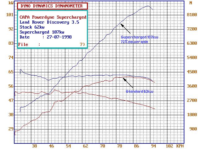
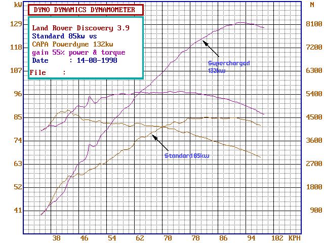
did the site have a graph for the V8?
"How long since you've visited The Good Oil?"
'93 V8 Rossi
'97 to '07. sold.
'01 V8 D2
'06 to 10. written off.
'03 4.6 V8 HSE D2a with Tornado ECM
'10 to '21
'16.5 RRS SDV8
'21 to Infinity and Beyond!
1988 Isuzu Bus. V10 15L NA Diesel
Home is where you park it..
[IMG][/IMG]
YarnMaster
SubscriberIs this what you're after?Originally Posted by Pedro_The_Swift

and here is one for 3.5
Hello all,
For some reasons, the pictures that were in the TD5 description are pointing to Discovery Owners Club :: Welcome to the Land Rover Discovery Owners Club. If any of you have acces to that site, can you then please re-post the thread with pictures?
Thanks in advance,
Regards,
Sandu
 Posting Permissions
| Search AULRO.com ONLY! |
Search All the Web! |
|---|
|
|
|


Bookmarks