

 Reply With Quote
Thanks mate.
I am looking at doing similar but did not want to shell out $400 for a VDO unit.
Nice neat install.")

 TopicToaster
Subscriber
TopicToaster
SubscriberJust finished putting my EGT gauge in Oscar, and I reckon its come up good enough to post a quick tutorial.
Its my first tute, so be easy on me
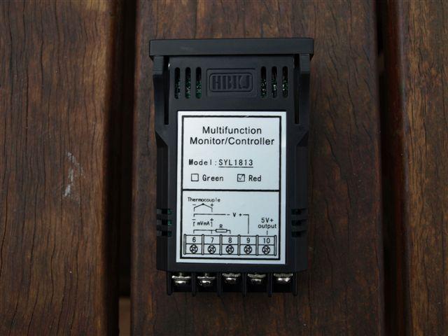
I got my gauge and probe online from Auber Instruments. auberins.com, Temperature control solutions for home and industry
They describe it as a Automobile Multimeter as it can measure EGT, boost, oil temp etc. Only one sensor can be connected at a time, meaning its not like a Madman EMS.
Here is the gauge side view (front piccy's later):
I also purchased a K type thermocouple from Auber, with a weld-in boss so that I could fit it to the EGR blanking plate. If you dont have the facility to weld it in you'd be better off with a threaded boss and just tap it into the plate.
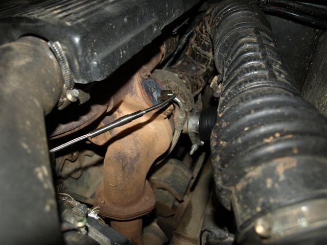
I welded it in on an angle so that I didn't have to bend the probe inside the manifold, as the hole in the manifold isn't perpendicular to the blanking plate.
As far as gauge location goes, I decided to remove the standard D1 clock and put the gauge in its place.
Remove the clock by first removing the drinks tray, and then releasing the tabs on the clock and unplugging it, along with the plug on the hazard lights switch.
Once its out ,I removed the face by releasing the plastic clips that hold it on (3 sets - end/middle/end).
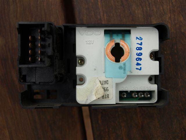
Here is the face removed, and you can see I've started to enlarge the hole to take the gauge:
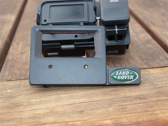
and then removed the 2 screws that attach the clock to the rest of the assembly.
NOTE: There are 4 screws - 2 that hold the clock to the assy, and 2 that hold the clock together. The holes in this picture are from the screws that hold the clock to the assy. Dont remove the other ones in the picture or the clock WILL fall apart!
There are also a couple of plastic clips that hold the clock to the rest of the assembly and these need to be released to finally remove the clock.
The next job is to gently enlarge the hole in the clock face until the EGT guage slides nicely into it. There are clips on the guage that will lock it in place once it slides in.
Take it slow doing this - if you make the hole too big the guage won't clip in nicely and you will have to find another method to retain it.
Here's what mine looked like once fitted in the original clock face:
Time to fit the face back onto the main assembly.
I came across a small glitch at this point. The clock face originally relied on the thickness of the clock itself to provide a nice fit with the main assy, and was loose when fitted without it. I cut out a small piece of plastic (any material will do) the same thickness and shape as the clock and mounted it on the original clock mounting screws. When the face was re-fitted the plastic took up the original gap from the clock and it wasn't so loose. A couple of dabs of silicon made sure it wasn't going to rattle. Forgot to take any photos at that point.
All thats left now is to run the thermocouple wiring in the engine bay and through one of the firewall grommets, and hook it up to the gauge along with some power.
I took the power from the clock connector plug, by making up some pins to insert into it from some 1.6mm welding wire. I cut a small length of welding wire and crimped it into a straight automotive joiner, then crimped the other end onto some wire to connect to the gauge. Worked really well and saved having to tap into something else. One of the wires to the plug is only live with the ignition on, so it worked out perfectly.
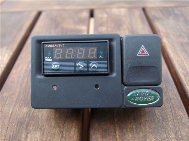
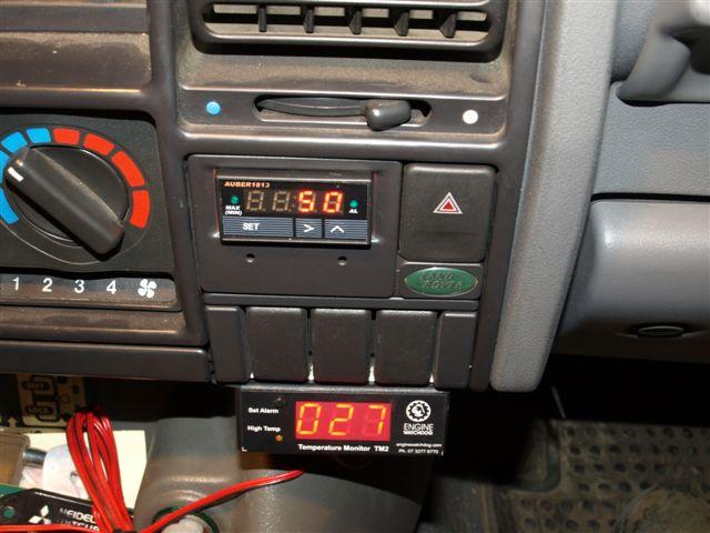
Here's the finished product:
Hope you've had an interesting read.
Steve
ChatterBox
Thanks mate.
I am looking at doing similar but did not want to shell out $400 for a VDO unit.
Nice neat install.
YarnMaster
SupporterYeah I second that, looks factory.
Carlos
1994 Land Rover Discovery 300tdi
1963 Land Rover Series 2a 88
Youtube Channel: https://www.youtube.com/channel/UCu3...BtsNIuTyGkAo5w
Instagram: https://instagram.com/rover_tasmania/
Wizard
cool love it ordered mine tonight a whole $90 del
AT REST
What size "K Type Thermocouple" did you buy, I noticed there are a few different length probes available, Thanks, Regards Frank.Originally Posted by steveG

YarnMaster
SubscriberAll the K type Thermocouples I could see on the site were limited to 400Deg C.. is that going to be enough or am I missing something?
BTW, I'm so going to have to get a PID for my Silvia* while I'm there
*NOT a nissan
Hercules: 1986 110 Isuzu 3.9 (4BD1-T)
Brutus: 1969 109 ExMil 2a FFT (loved and lost)
TopicToaster
SubscriberI used the "EGT Sensor - Weld In" from the "Automotive Instruments" page.
Heres a link, but not sure if its going to work for you:
Automotive gauges, EGT Boost : auberins.com, Temperature control solutions for home and industry
I was a little concerned that it wasn't going to be long enough, but having driven over 1000k's on the weekend I can say that its very responsive so I'm pretty sure its OK.
On mine I get 360-370degC cruising at 100k on flat freeway, and if I lift my foot slightly it drops a few degrees instantly.
Flagg - yup, you're missing something. Either go to the page above, or the second page from the "Thermocouples" menu. There are definitely ones that are good up to 1000degC.
Steve
Wizard
SubscriberI've just ordered my meter, thermocouple and a 3 bar map sensor from Auber. Having the map sensor means I'll be able to measure boost as well as EGT (but not at the same time).
I'm going to mount mine in the switch blank panel below the clock. With the blanks removed, there is an opening that is the perfect size to take the meter. Will post pics once it's done.
-- Paul --
| '99 Discovery Td5 5spd man with a td5inside remap | doesn't know what it is in for ...
| '94 Discovery Tdi 5spd man | going ... GONE
TopicToaster
SubscriberI also bought the MAP sensor, but haven't had a chance to play with it yet (along with another short thermocouple to use for the auto temp).
Make sure you take a few piccys of how/where you fit the sensor and post them up.
Steve
Wizard
SubscriberI have it installed now - works well. I have taken pics, but I'm having issues adding them to my gallery to post. Hopefully the problem will be sorted soon.
-- Paul --
| '99 Discovery Td5 5spd man with a td5inside remap | doesn't know what it is in for ...
| '94 Discovery Tdi 5spd man | going ... GONE
 Posting Permissions
| Search AULRO.com ONLY! |
Search All the Web! |
|---|
|
|
|


Bookmarks