
Originally Posted by
PhilipA

Khos, that is a captive nut.
You undo the bolt from the front side. I think it is 1/2 AF AFAIR.
You can do it without the dizzy taken off but it is a nuisance.
SO do this.
Get some Tippex or similar then draw a line on the body onto an adjacent part of the engine so you can put it back how you took it out.
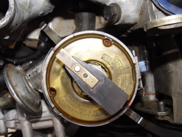
THEN mark the cap and the base of the dizzy . It only goes on one way but better safe than sorry.
THEN turn the engine to TDC firing which should have the mark at the crank pully at the TDC mark and the rotor should be pointing forwards but at no 1 plug wire. No 1 is the plug at the passenger side front. Mark this on the dizzy body.
The rotor will turn about 30 degrees as you pull the dizzy out so put a mark at the point on the dizzy where the rotor points once you have pulled out the dizzy . This helps you start at the correct place.
Mark the plug number on each plug lead either with tippex or on a bit of masking tape before you pull out any wires from the dizzy. The LH passenger set are 1 3 5 7 and the RH is 2 4 6 8 .
OK
YES
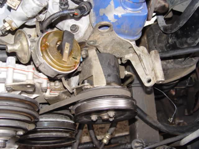
You can see the sneaky allen bolt behind the bracket. Plus tehre is a nut on the front head bolt which is a special bolt with a nut then a thread for another bolt so you have to remember to do the final tension before putting the bracket back on.
Regard sPhilip A


 Reply With Quote
")


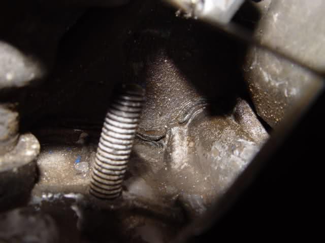
 There is a Bolt that Holds the bracket underneath the Pump and I think it's 15mm and it's B#@$^%y Tight, I suspect it can't be undone until the Belt tension has been removed ??? any ideas ?? Please see the pic below
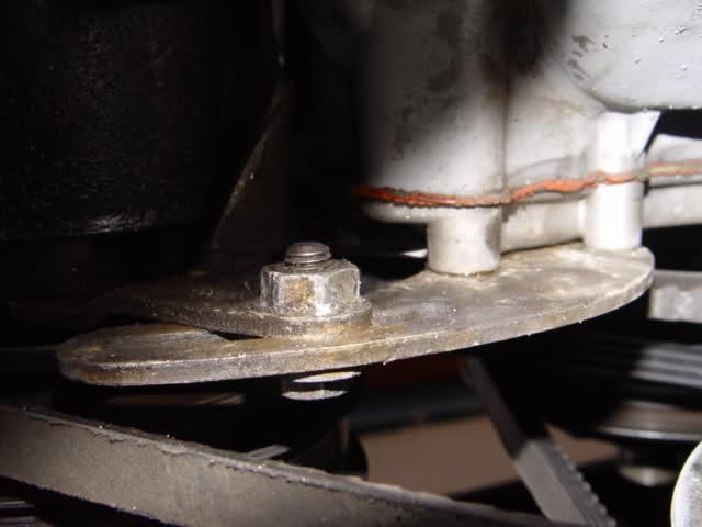

Bookmarks