
Originally Posted by
wrinklearthur

Hi Slug_burner
Thanks for finding those photo's, I wanted to keep this in this thread as it relates to the strength of Land Rover diffs in general, (Fifty lashes shall be received by yours truly if I am out of order).
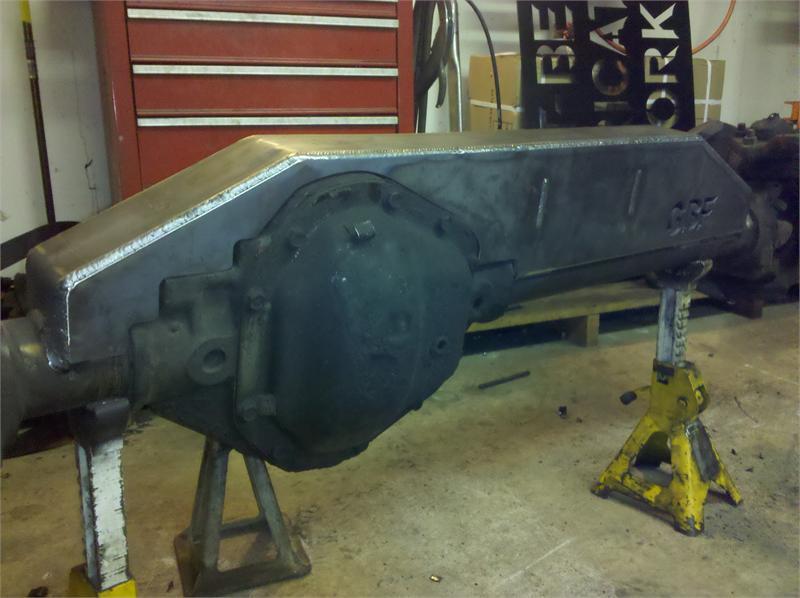
All of those mods are heavy without addressing properly the issue of the tube breaking where it enters the diff centre casting.
I will write this next part as a demonstration for youngsters, so please don't feel annoyed at the simplistic description, instead grab a twelve year old and go through doing the model with him/her.
For way of an illustration, play with a milk carton, a couple of pencils and a sheet of paper.
Lay the carton down, puncture the carton each side with the pencils so the holes are opposite.
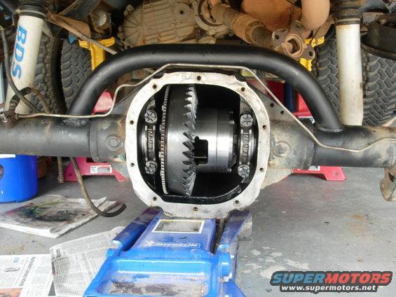
Try and lift the carton using a finger under each pencil and the pencil's will bend up, the weakness is the wall of the carton, relate that to the Salisbury where the tubes enter the diff centre housing.
The next thing to try, is to strengthen the joint on our milk carton model using a sheet of paper, lay the paper over the top of the carton, emulating the bracing using in the photo's, pull the pencils out and puncture the paper and reinsert the pencils back into the carton, then move the paper so that the holes in that paper are moved away from the carton sides and the paper pulls tight across the top of the carton.
Now repeat the lift and you will see that that paper doesn't offer any resistance to the upward motion of the pencils.
The last part of this experiment is placing that paper under the carton, doing what I have already explained, but pulling the paper tight under the carton. If your model is working correctly, the paper should offer resistance to the upward motion of your pencils.
So for a truss to work on the Salisbury, it should be underneath the diff centre and needs not to have the weight or size of those constructions shown in the photo's.
.


 Reply With Quote

Bookmarks