

 Reply With Quote
Sounds like a similar location to mine.Originally Posted by karlz


 Master
Supporter
Master
SupporterI mounted two of the traxide relays to a thin metal plate.
The thin metal plate was attached to a left hand side bracket that connects the left wing to the body. Its quite near the heater blower plastic intake.
Sorry no pictures.
Could you get 3 traxide size relays on that plate? Probably just, a piggy pack solution might work better.
I preferred in bay rather than behind the headlight because 1. easier to get at, 2. a bit higher.
If you really need a pic to explain where I stuck it let me know and I'll take one.
2015 Defender 110
Wizard
SubscriberSounds like a similar location to mine.
'51 Series 1 80"
'12 Defender 90
Master
SupporterYep same place
2015 Defender 110
TopicToaster
SubscriberHow did people route the larger gauge, relay output wires between the headlights?
Under / around the radiator or over the top of the rad core (under the top fan cowl cover)?
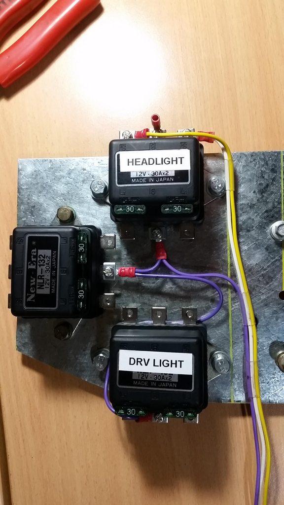
Teaser pic.
Been busy working on a mounting solution. Trying to do most of the wiring out of the vehicle, and have a somewhat plug'n'play solution to drop in when it's all done.
The only wires connected so far are the relay coil earths (purple) and the piggy-back coil signal connector wires from the factory headlight socket.
-Mitch
'El Burro' 2012 Defender 90.
YarnMaster
Hi,
From memory, across the back of the radiator.
The driving lights went across the bottom of the radiator, on the pierced grid shroud metal bit.
Should have the driving lights in soon, had to make up some brackets to go between the lights and the ARB bar mounting points, which are only a single hole, and too far forward.
A lot more work than I expected.
Cheers
ChatterBox
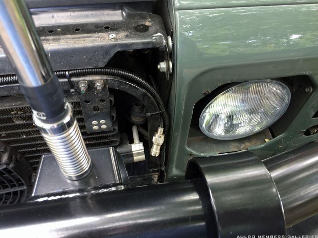
SubscriberAcross the top of that bent, square tube in front of the radiator:
There are holes on the inside of the wings conveniently located to run the wiring through. The wiring for the driving lights came out of the same hole and into the bullbar. I can take some more photos if that's not clear enough.
Cheers,
Jon
TopicToaster
SubscriberThanks Jon
I'll 'eyeball' the wire run, which will give me the required lengths to make some more cuts on the traxide kit and complete the enxt few wire hook-ups.
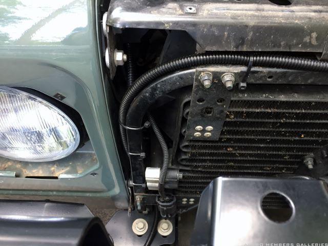
As for the 'hole' are you refering to the 2 small holes on the far right on the flat (inboard) panel pictured below, or the gaping chasm of the wing strcutrure to engine bay?
F899066D-4C32-401C-82D6-624F399FA9F9_zpsxxzuj5f6.jpg
Cheers.
-Mitch
'El Burro' 2012 Defender 90.
ChatterBox
SubscriberI think it must be the larger hole at the bottom far right of that flat panel.
TopicToaster
SubscriberYeah, so it turns out if you undo the tabs on the H4 headlight connectors, they can be removed from the plastic casing, and can then be fed thru the aforementioned holes. For me at least they wouldn't fit in their supplied state.
Im building the headlight and driving light relays and loom sections bit by bit on the bench, and will install all power and earth wiring on the vehicle afterwards. I live on th edge like that.
-Mitch
'El Burro' 2012 Defender 90.
YarnMaster
Hi,
As per previous post, I ran the loom across the top of the radiator.
Cheers
| Search AULRO.com ONLY! |
Search All the Web! |
|---|
|
|
|


Bookmarks