

 Reply With Quote
So, does that mean all we need is that switch then we can connect up and have dashlight dimming?Originally Posted by clubagreenie


 TopicToaster
Thats the switch.
YarnMaster
So, does that mean all we need is that switch then we can connect up and have dashlight dimming?
D4 MY16 TDV6 - Cambo towing magic, Traxide Batteries, X Lifter, GAP ID Tool, Snorkel, Mitch Hitch, Clearview Mirrors, F&R Dashcams, CB
RRC MY95 LSE Vogue Softdash "Bessie" with MY99 TD5 and 4HP24 transplants
SADLY SOLD MY04 D2a TD5 auto and MY10 D4 2.7 both with lots of goodies
Master
Let's hope it's that easy.
Can anyone confirm please?
TopicToaster
Well I've compared mine to another with it fitted and I have the socket for it. But while it looks ok it's the plug looks more like the type fitted in RRC's than Disco's, but the plug looks like the pic in the book also. I'll have another look under dash tomorrow. Maybe ask seller for part #, should be AMR 2745.
YarnMaster
You're a good lad!!!
Last edited by gavinwibrow; 2nd August 2012 at 06:09 PM. Reason: typo
D4 MY16 TDV6 - Cambo towing magic, Traxide Batteries, X Lifter, GAP ID Tool, Snorkel, Mitch Hitch, Clearview Mirrors, F&R Dashcams, CB
RRC MY95 LSE Vogue Softdash "Bessie" with MY99 TD5 and 4HP24 transplants
SADLY SOLD MY04 D2a TD5 auto and MY10 D4 2.7 both with lots of goodies
Master
Just found this. As Graeme referenced in post #7 above...
Thanks Graeme.
TopicToaster
Fossicker
The wiring and connector for the dimmer control are only fitted to NAS and Jap versions of the DII.
It's pretty simple to add the connector to the loom.
The connector, as someone said above, can be found in Range Rover Classics, as well as most Austin-Rover cars of the 80's - Maestro/Montego - but, I'm not sure if you got those in Australia? (you weren't missing much, if you didn't)
It's a RISTS 3-way female TTS connector.
I recently made-up an add-in harness for the dimmer control, for a Swedish member of the D2 Boys Club Forum, to fit into his LHD DII.
These are the instructions I sent him -
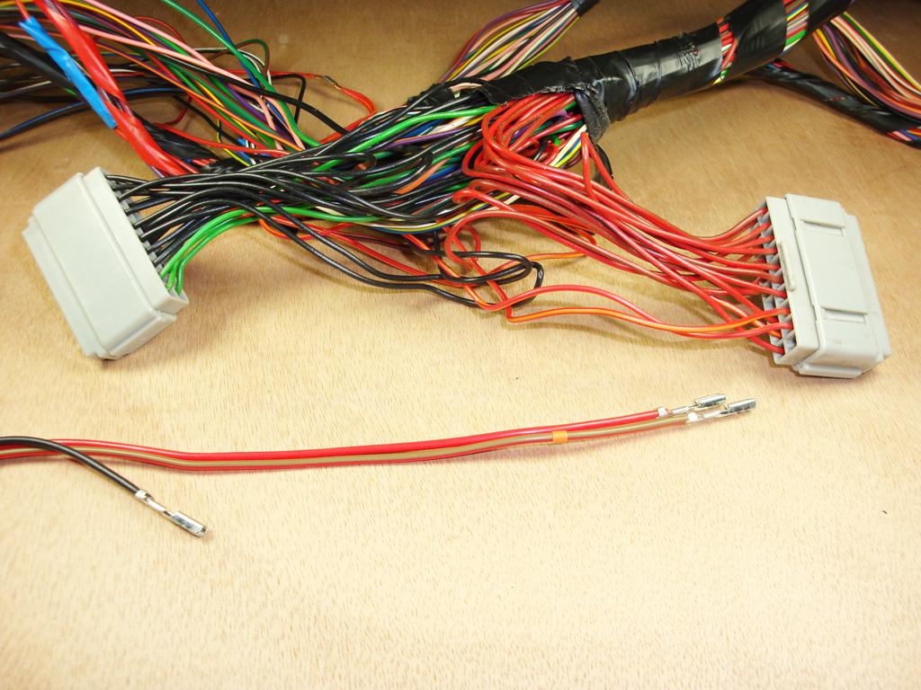
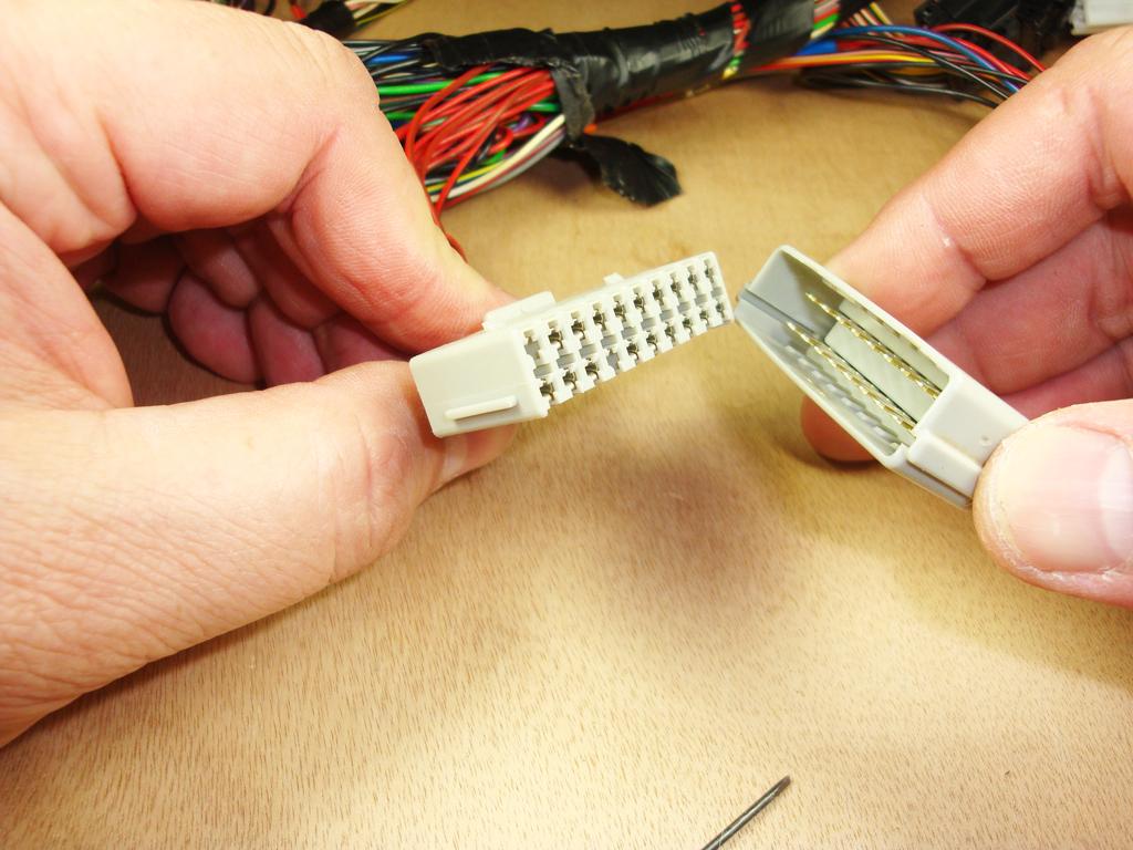
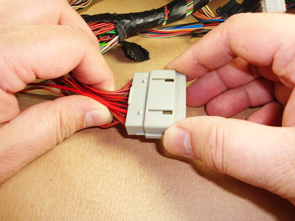
Here are the pictures of connecting a Dash Dimmer Harness into the Headers C0759 and C0760 behind the Instrument Pack.
In the pictures, I'm using a RHD facia harness (and a LHD Dimmer Harness), I've 'flipped' the facia harness, so that it looks like a LHD one in the pictures.
The facia harness has also had some of it's binding tape removed, which is why it looks like a loose bundle of wires in places.
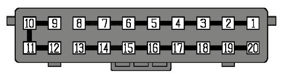
In RAVE, Land Rover number a connector's cavities from left to right on the front (face) of the connector.
So, for clarity, I've modified a Grey Header diagram, to show the cavity numbers from the cable-entry side of the connector -
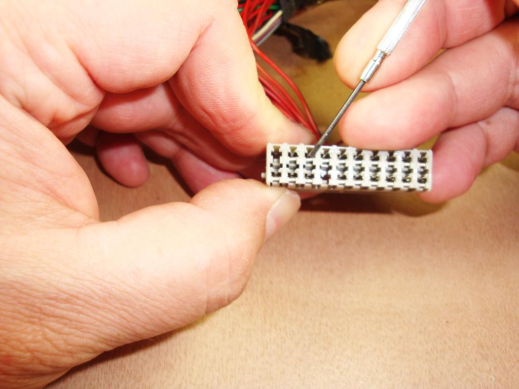
We'll start with C0760
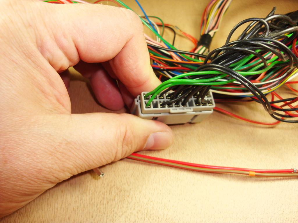
Pointing at cavity 12, which is one of 4 terminals on the LG sub-circuit (Instrument Pack Live) - we'll avoid connecting to this")
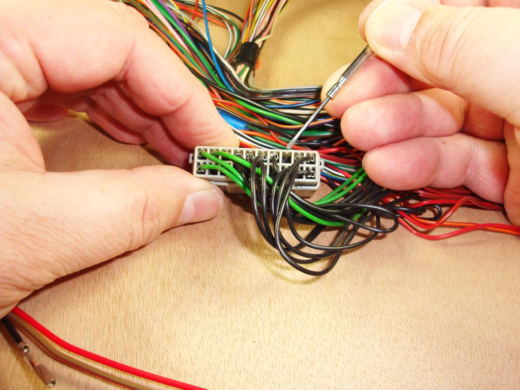
Pointing to cavity 3, where the dimmer's earth will be connected to -
Next three pictures - Inserting the Dimmer Harness earth terminal (Black wire) into cavity 3, note the orientation of the terminal -
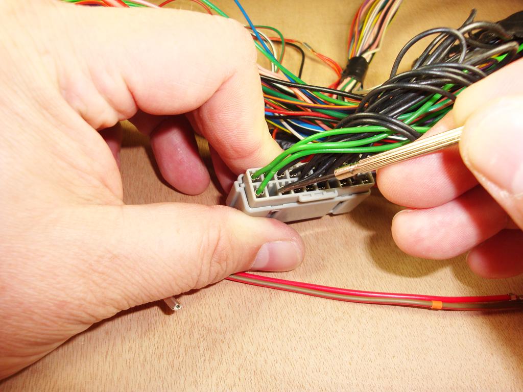
Now C0759
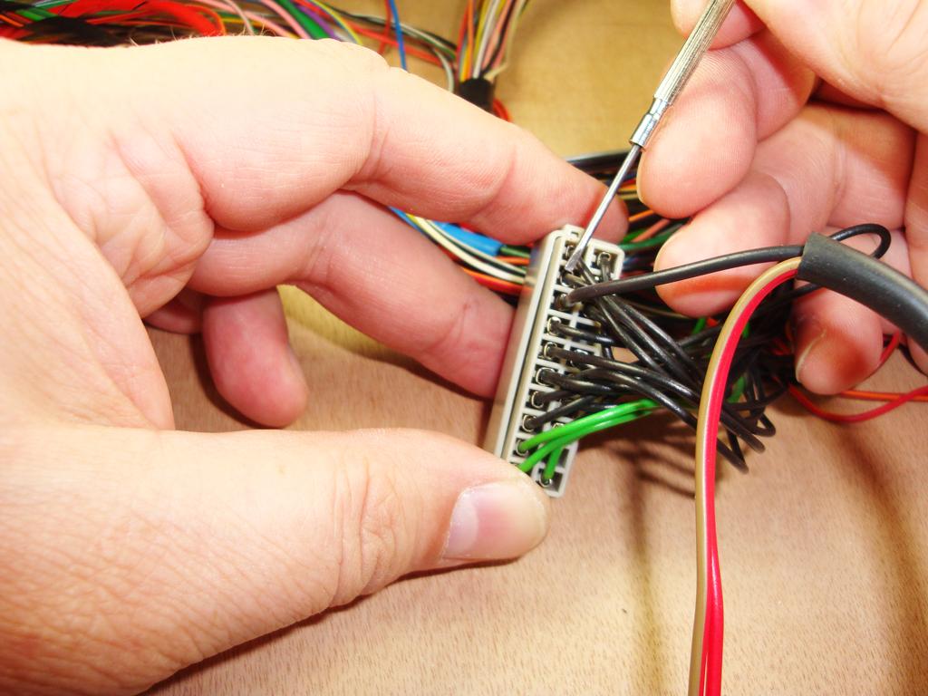
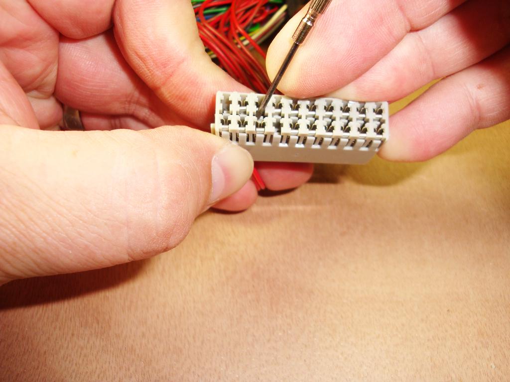
Pointing to cavity 12 on the illumination feed circuit on Header C0759, note the empty cavity 11 next to it, we'll be using that cavity soon -
Pointing to cavity 13 on the switch and instrument illumination circuits on Header C0759 -
On non-dimmer vehicles, terminals 12 and 13 of are connected together by a loop of Red/Orange cable, this loop connects the illumination feed circuit (terminal 12) to the switch and instrument illumination circuits (terminal 13).
This loop also has a splice off of it, which powers the headlamp levelling circuit, via the headlamp levelling switch (more of this later)
On vehicles fitted with a Dash Dimmer, the dimmer's input and output go between terminals 11 (same sub-circuit as terminal 12) and 13.
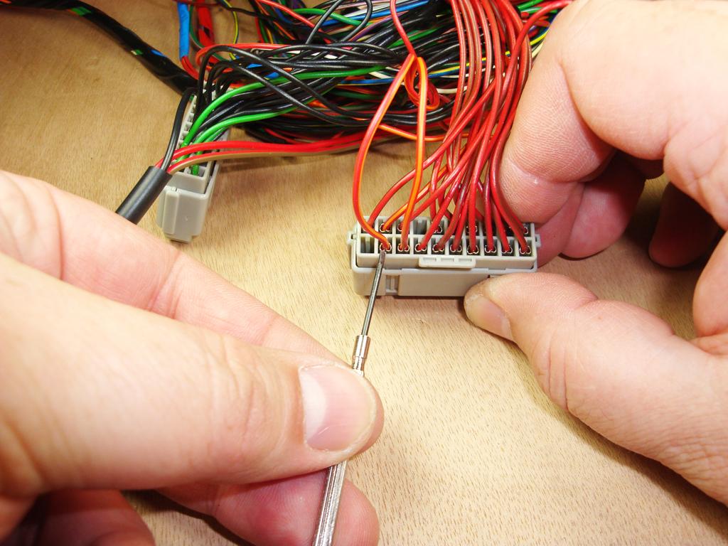
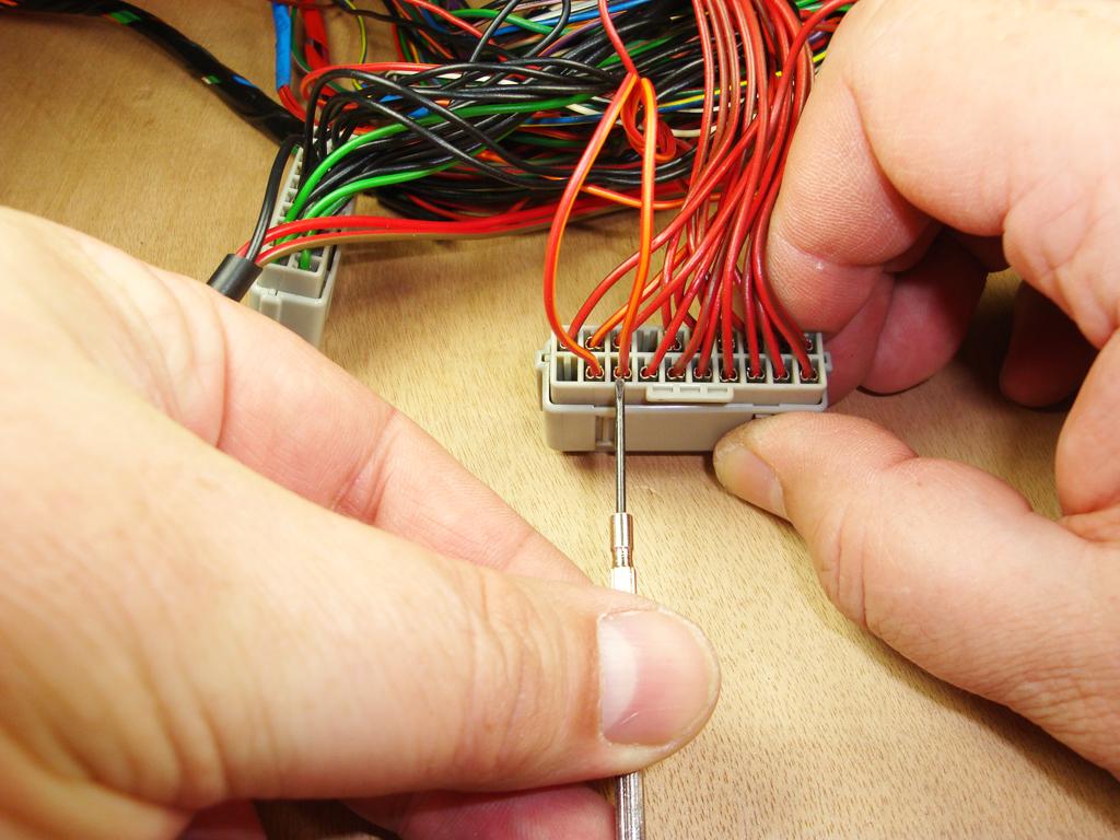
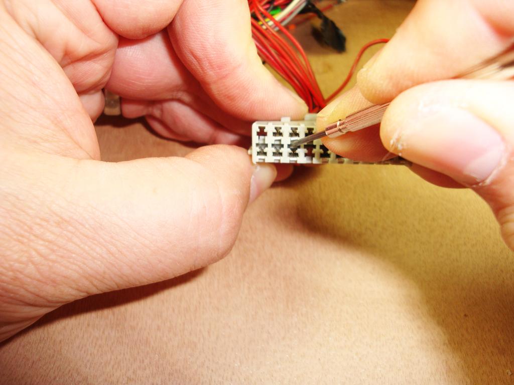
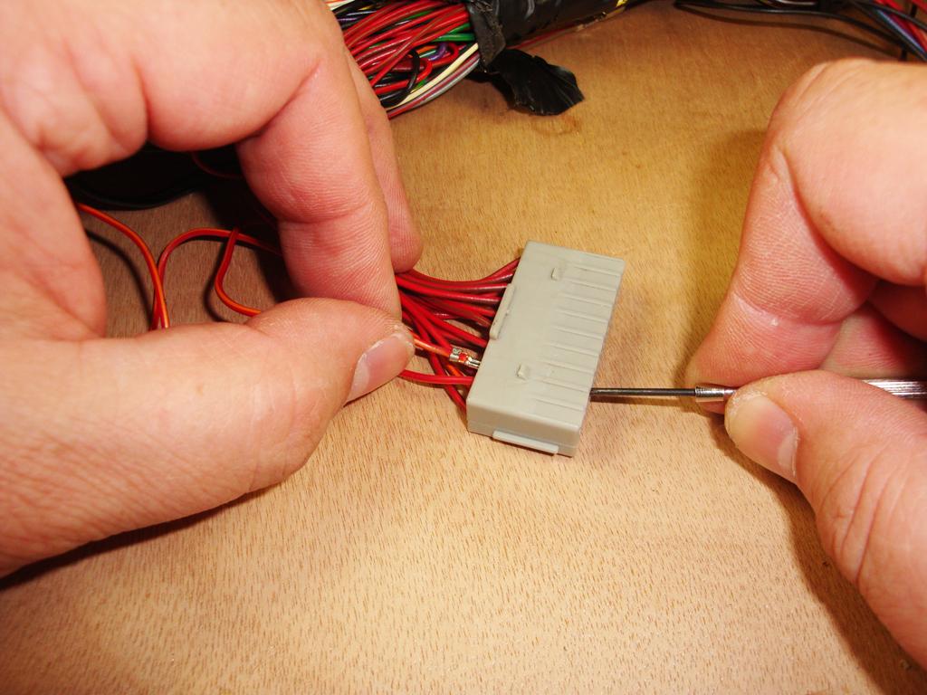
We will need to release the terminal in cavity 13 - lever the splice cap away from it's latches on the connector body -
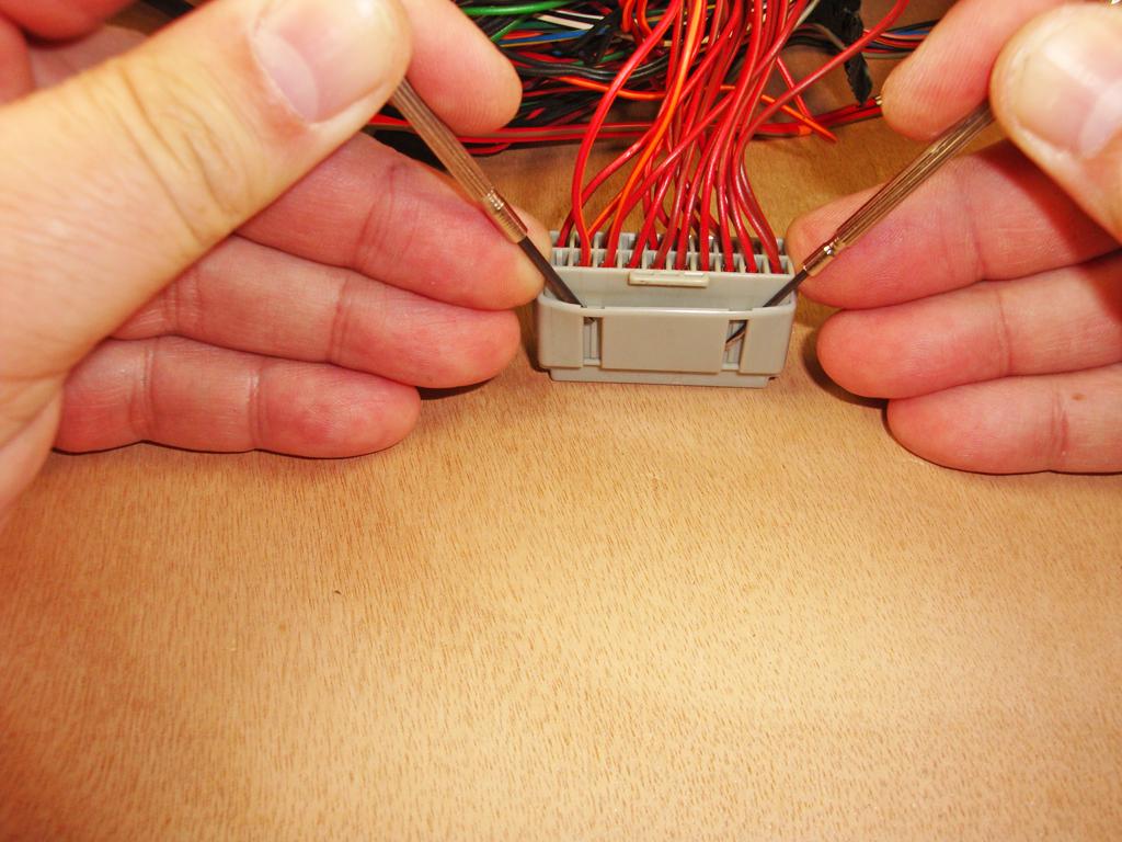
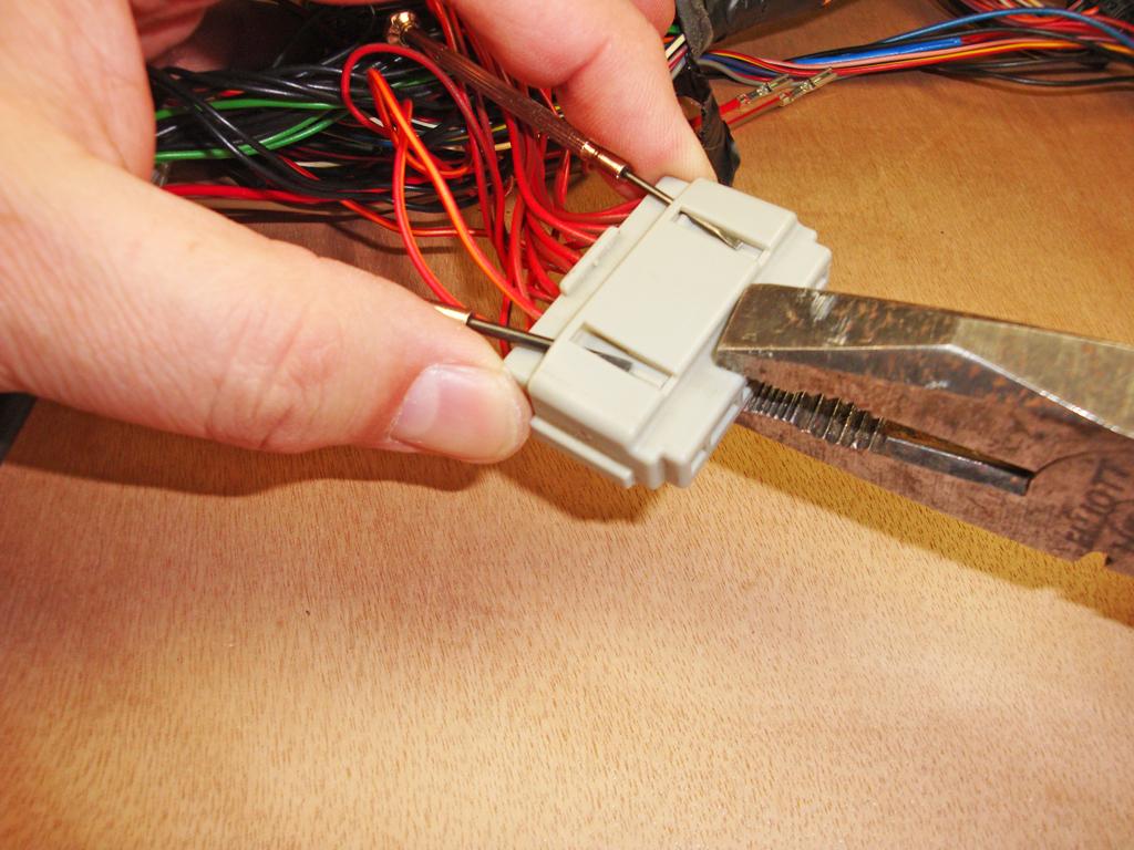
With the side of the splice cap lifted above the latches, hold the connector body and pull the splice cap with a pair of pliers, it may help to wiggle it, or pull from each end alternately -
Done
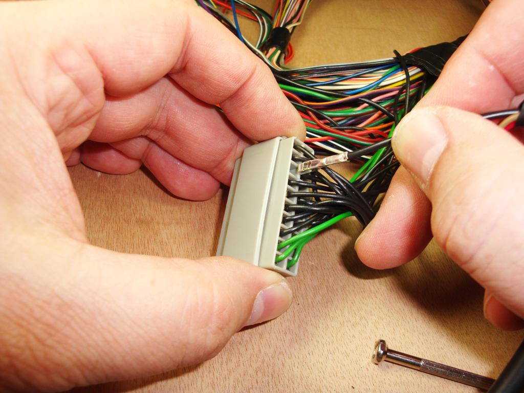
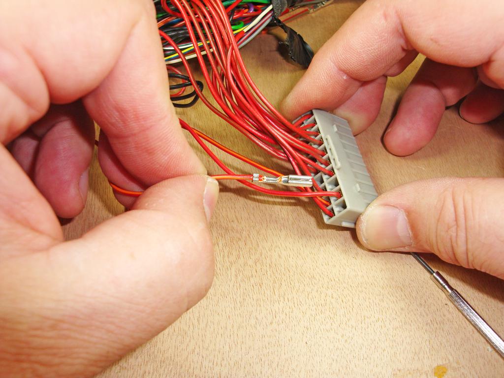
From the front of the splice connector - pointing to the terminal in cavity 13 (you can see the plastic retainer below it) -
Next 2 pictures - Depressing the plastic retainer to release the terminal -
Terminal released from cavity 13
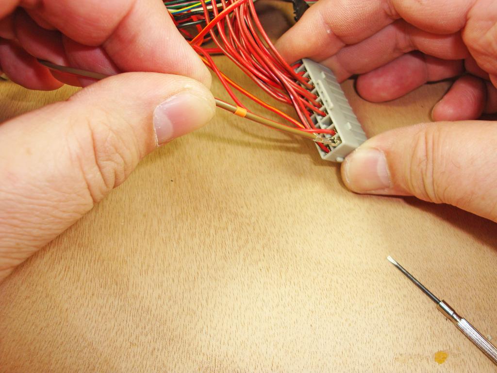
The other end of the Red/Orange wire in the terminal removed from cavity 13, is connected to the terminal in cavity 12 (illumination feed circuit), which is also connected to the headlamp levelling switch (via splice A56 in the loom) to supply it's power for headlamp levelling. This terminal should be taped-up, to insulate it, and taped back to the facia harness -
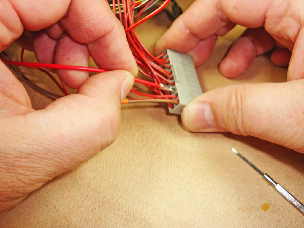
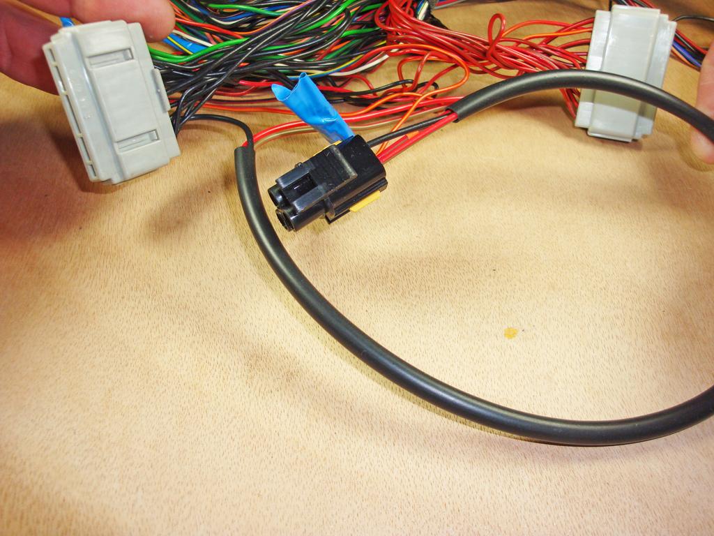
Connecting the Dash Dimmer Harness
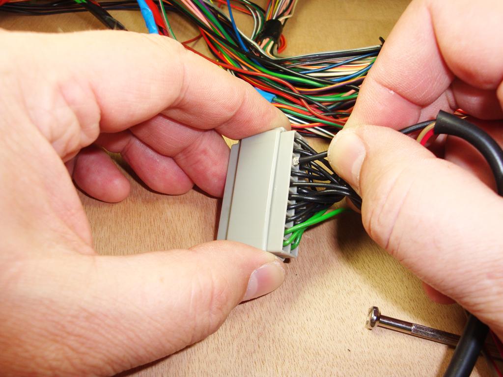
Insert the terminal on the Red/Brown wire with the Orange band (I didn't have any Red/Orange cable, I do now) into cavity 11 on C0759 (note the terminal's orientation) -
Insert the terminal on the Red/Brown wire into cavity 13 on C0759 (note the terminal's orientation) -
Replace the splice cap onto C0759 -
Job done - you can now plug-in your dimmer control -
Photobucket!
Paul.
1989 Arles Blue 2.5TD 110 Hardtop
1999 Epsom Green Discovery II 4.0 V8i 'XS'
.
Last edited by PaulMc0308; 10th August 2017 at 06:57 PM. Reason: Putting the pictures back
YarnMaster
SupporterHow do you get behind the dash facia to fit the switch?
Swaggie
Lower the steering wheel to its lowest position then remove the 2 screws in the lower front of the facia surround. The facia then pulls straight back towards the driver and IIRC it unclips along the windscreen side. The switch plugs will only fit their particular switch, for each side at least, so no opportinuty to put them back to the wrong switch.
MY21.5 L405 D350 Vogue SE with 19s. Produce LLAMS for LR/RR, Jeep GC/Dodge Ram
VK2HFG and APRS W1 digi, RTK base station using LoRa
 Posting Permissions
| Search AULRO.com ONLY! |
Search All the Web! |
|---|
|
|
|
Bookmarks