-
25th February 2014, 02:46 PM
#1
-
25th February 2014, 09:41 PM
#2
Hey, Looks great. whats the duty cycle of the compressor? One benefit to the tank is that it acts as a cooling chamber, as the compressed air (which heats as compressed, Charles Law?) expands it cools again (maybe a water separator after and keep an eye on water levels in the tank). Where does the valve box mount? Also if you have a winch, consider a line to pressurise the gearbox & motor to keep water out. Just needs to be a few psi.
For the volume you'll have stored it's the water capacity (marked on cyl as WC) X pressure in Atmospheres. So your 1L @ 145psi (10atm) gives you 10L @1atm).
Sorry for not calling back when I was up. Started drinking at 0900 and went downhill from there. Monday got RBT'd coming home from dropping the kids off and was still 0.01! if that's an indication.
I made a mount for my compressor and valves for the winch air clutch in the same place. Fits on all original holes.
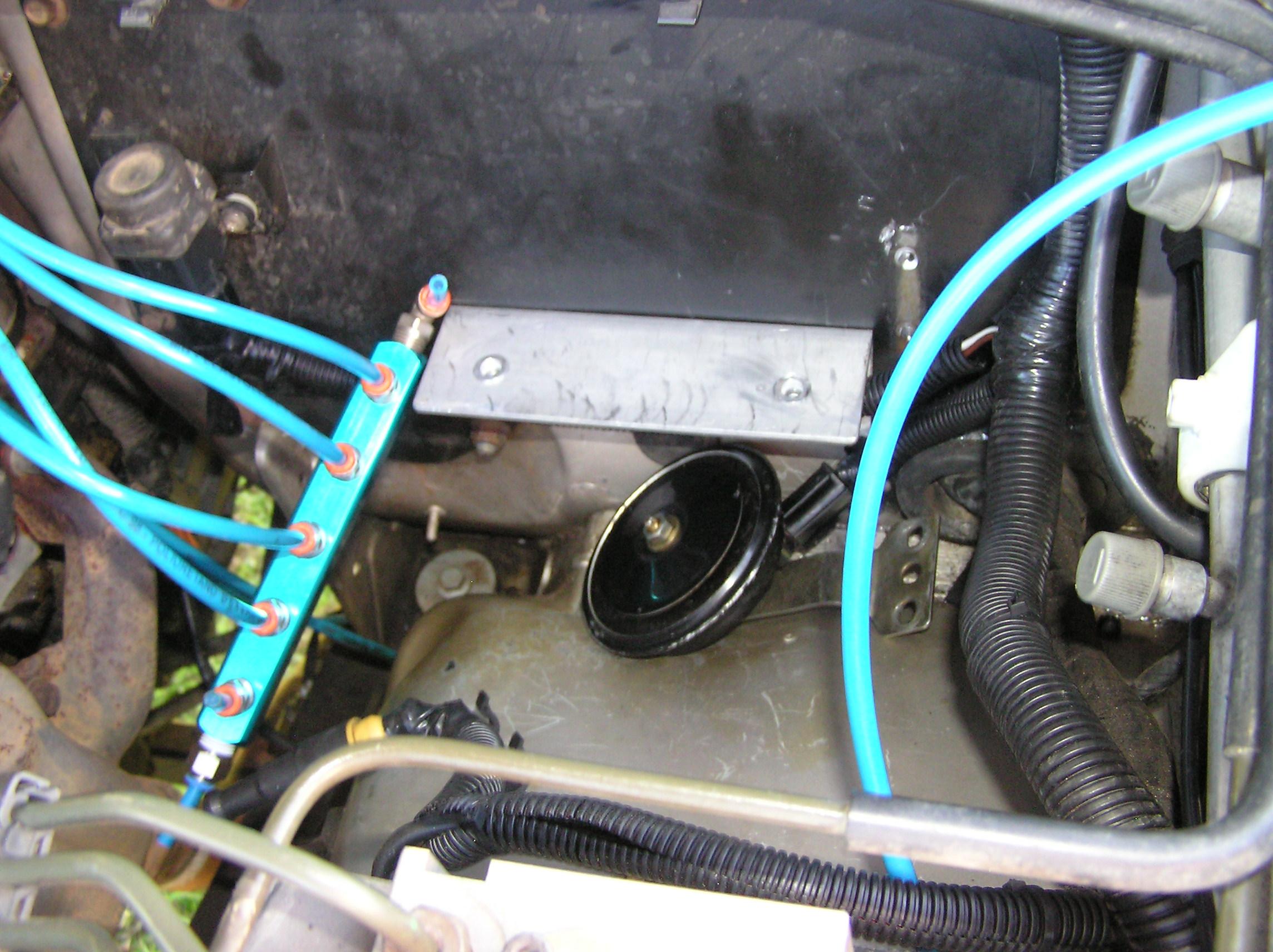
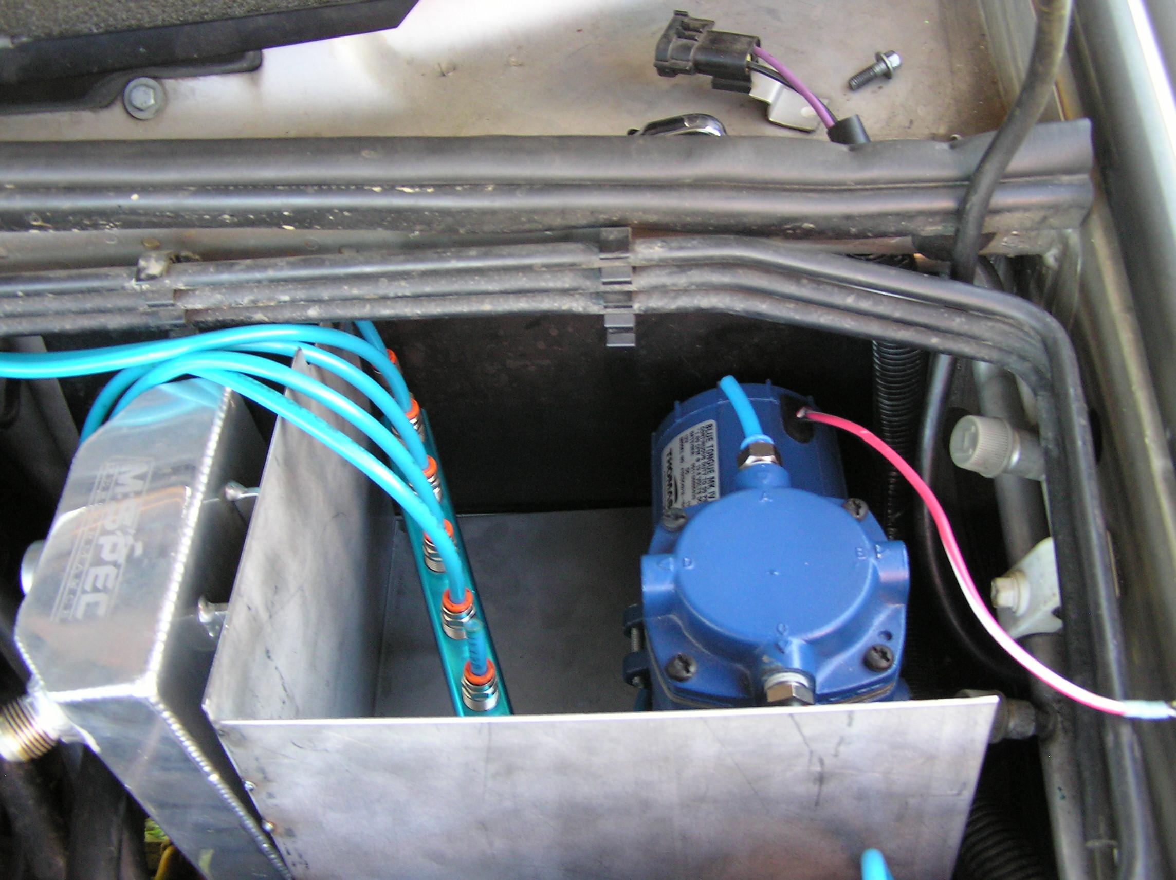
With the manifold for the breathers, blue lines, F&R Diffs, Auto, Tfr, Fuel. collects here and runs a single line out & up the snorkel. The catch can for the engine sits on the side, breathes from both rockers and the back of the engine valley. Compressor draws from the cabin air (not finished here) and runs to a tee that has a ryco fitting for inflation plus into a solenoid for the winch clutch. This is powered from a master switch in cabin for the winch power which also cuts the winch solenoid power.
Finally have it back on the road, albeit with about a dozen more things to be claimed back on insurance extras. Just little things like auto cooler, A/c (killing me ATM), body moulds and a claim for a replacement engine.
Hope yours is going well.
J
-
25th February 2014, 10:02 PM
#3
Compressor is a VAIR 380C. It's 100% duty cycle with a max pressure of 200psi. Down side is it doesn't flow as much as some of the others.
I wanted a blue tongue like yours but $$$ the VIAR won. I figure they use them on the bouncing low rider trucks so they cant be that bad and rebuild kits are readily available (that could also be bad as to why they are needed).
The valve box is the original compressor box. Mounts to the chassis rail just as it always did.
My winch is apparently sealed to IP68 which is closer to water resistant than waster proof but I'd be more worried about blowing the seals out with any pressure than keeping water out. It's a Smity Built XO2 winch.
10atm is great but. I googled how many litres in a tyre and got all sorts of results. If we say 100 litres in my 245/75/16 then that 10atm is only enough to get me to 1.47psi as 1atm is about 14.7psi an I only have 1/10th of a tyre stored.
No worries about the call. I can't remember what I got up to. As for you drinking, Darwin will do that to you.
I still have to work out where/how to mount the alarm horn. Shouldn't be too hard.
I like your idea of taking air from the cabin. I was going to run it the air box and seal it in but the air in the cab is usually dryer as the A/C runs when ever the vehicle is running up here.
Happy Days.
-
25th February 2014, 10:57 PM
#4
Very neat and well laid out! looks to be a better mouse trap all round! You may find moisture build up in that small tank to be a problem, though taking the air from the cabin will help. Probably the main use of the tank will be to iron out pressure pulses from the pump, which do have an effect on valves. 100% duty is a far cry from the factory 5! 
Cheers Scott
-
25th February 2014, 11:05 PM
#5
At least 1 and maybe 3 silicon dryers are in the plans but I just don't have them yet. Haven't even ordered them yet. It has been a slow process getting this stuff together as when everything is working I don't get very motivated to fix it. It just hasn't been working as well as it can. I've been manually filling and letting down the bags as needed. My disco being off the road while I wait for a new radiator to come from the UK has been my motivation.
I plan to use silicon canisters just like LR do. They'll absorbed the moisture from the air between the compressor and the air tank and then the dry air coming out of the air tank will dry the silicon. The other 2 I'm thinking of putting inline to each of the bags.
Happy days.
-
25th February 2014, 11:33 PM
#6
For the alarm horn modify the bracket and lay it flat under the compressor. Mines fixed to the angle bracket that holds the base of the box in mine. You need to flatten it out though (the bracket).
And desiccant gel doesn't dry in air. Needs heat, low oven with the door ajar to let the condensate out.
-
26th February 2014, 04:57 PM
#7
Well it's all in and working today. Well sort of. My radiator only arrived this afternoon so I haven't been able to start it and test "Off Road Mode". All I get is 3 chimes when I press the button.
I have been able to set the height with Nanocom. Again, well sort of. It's not parked completely level and I cant move it because the new radiator isn't in yet.
While setting the height, I set the height really low and then set it high and it raises pretty quick. The air in my tank is enough to lift it about an inch and half before the pump kicks in. It'll raise that 1 1/2 inches in 5 - 10 seconds which is awesome. I haven't timed it but once the pump kicks in it only runs for about 30 second to get the pressure back up in the tank.
I'll report back more once I'm up and driving around. I should get the radiator in tomorrow, weather permitting.
Happy Days.
-
26th February 2014, 07:25 PM
#8
There is a relay in the circuit (r0216 on the cct diagram) between the pump and the SLABS, so there can't be current sensing occuring on the pump. Valves may be a different proposition, as they are connected to the SLABS. More concern about drawing too much current I'd say, as the drivers would most probably be a MOSFET (?) with the design for a certain current draw.
-
26th February 2014, 09:16 PM
#9
Thanks "bsperka".
It's working and I'd had noticed that relay when I was working out which wire was + and - on the pump plug. The pump has a Brown and white with red line wires. I hadn't checked the vehicle side of the plug when I was trying to work it out from the circuit diagram. Turns out the vehicle side of the plug has a black wire which is obviously negative. As the valves have LEDs on them they are polarity sensitive.
The left and right valves are the standard LR valves and I haven't changed anything with them apart from their location. The valve that replaces the pump will obviously pull far far less current than the pump previously did so no trouble their.
The only place that could be a problem is the exhaust valve but these are pretty light duty valves hence why I had to use a regulator to drop the pressure getting to the valves as they wont open over about 110psi.
I was thinking about putting a second valve inline with the valve that replaces the pump as I thought that if this valve should stay open for any reason such as relay stuck or the valve itself stuck then I thought that air would continue to flow into the system and possible blowing a bag but it turns out that the left and right selection valves close when no air is needed anyway so those 2 valves become my fail safe for the "IN" valve.
Happy Days
Happy Days.
-
26th February 2014, 10:07 PM
#10
Just for anyone that wants to know. This is the cylinder thing that sits between the filter in the rear tail light and the compressor box. The exhaust also goes back out through this thing. It's about a foot behind the compressor box and well, it's empty. It appears that it could be some sort of muffler.
Happy Days


 Posting Permissions
- You may not post new threads
- You may not post replies
- You may not post attachments
- You may not edit your posts
-
Forum Rules
Search AULRO.com ONLY!
|
Search All the Web!
|


 Reply With Quote

Bookmarks