Page 2 of 4 FirstFirst 1234 LastLast
Results 11 to 20 of 35

Thread: DeBricking the NNN - an easier way?

  1. #11
    Join Date
    Jan 1970
    Location
    Melrose SA
    Posts
    2,838
    Total Downloaded
    0
    Paul
    Sorry didnt realise that C0658-33 was the ignition feed

    Duane

  2. #12
    Join Date
    Feb 2011
    Location
    Brunswick, Victoria
    Posts
    3,778
    Total Downloaded
    0
    Duane,

    I didn't realise either until I was looking at the circuit diagrams last night.

    Actually I glad you raised the question because it occurs to me that we might not actually need to power the pins attached to the main relay at all.

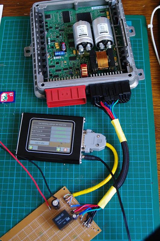
    Bear in mind that the ECU powers the glow plugs to 90V and the injectors to 85V, and the capacitors MadTom mentions appear to be related to a step up dc-dc convertor which I'd have to assume provides this power. There isn't much point running these sections of the ECU when we are bench flashing.

    I'll see if I can trace which power pins do what because I'm fairly certain we can reflash with only the CPU section of the board running. I'll do some investigating tomorrow so see if I can clear that point up.

    cheers
    Paul

  3. #13
    Join Date
    Feb 2011
    Location
    Brunswick, Victoria
    Posts
    3,778
    Total Downloaded
    0
    I spent some time today rigging up a ghetto powering rig, which I didn't manage to get working 100%. Sitting down to re-read RAVE I have spotted my mistake - I assumed the main relay line was supplying 12V from the ECU whereas it is actually completing an earth path - earthing both ends of a relay coil doesn't achieve very much. At least it's an easy fix.

    At this point I'm still not sure that I can power from IGN only. I did have a poke around with the multimeter with pin 3 powered, and it seems to power both the injector/glow plug circuits as well as the low level stuff. The two big capacitors supply different sections of the ECU - 3300uF 40V for 12V and 5V circuits and a 1000uF 100V for glow plugs and injectors. The positive pin of the 100V capacitor measured 91V so the rating is definitely needed.

  4. #14
    Join Date
    Feb 2011
    Location
    Brunswick, Victoria
    Posts
    3,778
    Total Downloaded
    0
    So after an afternoon or two of fun and games at chez OffTrack, I finally have the powering rig up and running, and the ECU debricked using the unsolder-program-resolder rigmarole. That is the good news. The bad news is the Nanocom flash upload is diabolically finicky as every. I have been able to upload factory maps with a reasonable degree of reliability but remapped .maps files are fairly hit and miss.

    In the end I dug out an old 1Gb SanDisk SDCard to see if that made any difference. After formatting and loading the .map file from a PC I was able to load the flash file on a second attempt.

    I'm finding that I need to allow the Nanocom to sit for a minute or two without power before booting then going straight to the Td5 Map utility. I'm finding more often than not the Nanocom chokes on the Protection Verify stage, which is prior to any communication on the OBD bus, so suggests the issues I'm having are probably related to reading the SDCard.


    I had a bit of a problem with the relay on the bench rig which took a while to sort. In the end I had to put a 220uF capacitor across the coil because the power supply was momentarily dropping to below 6V when I activated the "ignition" switch. Without the capacitor the relay would chatter as the voltage dropped causing the relay to open, then recover enough to close the relay again. The capacitor provides enough of a power reserve to prevent the relay coil dropping below it's trigger voltage. The down side is the relay can take 10-15 seconds to switch off after the "ignition" is turned off. At least you can hear the click of the relay. I'll probably add an indicator LED so it's clear when the power to the ECU is actually off.

    The line droop when first switching on makes it impossible to power the Nanocom from the rig so I'm using a 2A 12V supply that came with an old ADSL modem for that purpose.

    I picked up a variable voltage 15A supply from Jaycar, which I had thought would be a bit "stiffer" under load. The only time this is an issue is when you flip the Ignition switch. A big capacitor bank might solve this problem, that creates other issues, like long time delays before the charge drains. The pic below shows the PSU with the ECU fully powered. After the initial inrush current draw is pretty minimal.


    This is the "Please Wait" of doom If your flash upload fails after this point your ecu will need debricking.
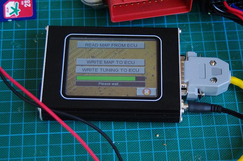


    In this case the upload finished.


    These are some of the more interesting default values. These are with no inputs to the ECU.


    Still waiting on the BDM interface to turn up so no progress on that front as yet.

    cheers
    Paul

  5. #15
    justfishing Guest
    Hello,
    I have been following this thread with great interest and you have put in lots of time in to it this is a great effort ..........you mention that you are having trouble with your SD card. I found that when i down loaded a .map file to my laptop (windows 7) and then copied to the SD card it never worked very well or took a couple of goes or more, had lots of trouble, but now if I down loaded from my email straight to the SD card bypassing the computer it reads it much better and usually the first time.

    Ian

  6. #16
    longclose Guest
    Hi Paul (Offtrack),

    Have just joined the forum as a result of the excellent post regarding the BDM work you are undertaking. I have bricked my ECU as a result of the underlying issues with Nanocom and the CAN comms on the TD5 (following all usual protocols) I have access to three other bricked ECU's from the local Landy specialist if required.

    Like you I wish to get the BDM process working for all Landrover owners who are trying to make use of the Nanocom and flash upgrade facility. Have you made progress on the BDM? I have got the BD32 and DOS environment working but lack the necessary software skills to modify the scripts to reflash the two 64K blocks on th AM29F200. I do have access to embedded developers if required to get this up and running with you if required. Drop me a PM if you want to work together on this...

  7. #17
    Join Date
    Feb 2011
    Location
    Brunswick, Victoria
    Posts
    3,778
    Total Downloaded
    0
    Quote Originally Posted by longclose View Post
    Hi Paul (Offtrack),

    Have just joined the forum as a result of the excellent post regarding the BDM work you are undertaking. I have bricked my ECU as a result of the underlying issues with Nanocom and the CAN comms on the TD5 (following all usual protocols) I have access to three other bricked ECU's from the local Landy specialist if required.

    Like you I wish to get the BDM process working for all Landrover owners who are trying to make use of the Nanocom and flash upgrade facility. Have you made progress on the BDM? I have got the BD32 and DOS environment working but lack the necessary software skills to modify the scripts to reflash the two 64K blocks on th AM29F200. I do have access to embedded developers if required to get this up and running with you if required. Drop me a PM if you want to work together on this...
    Email Sent.

    I ran in to a bit of a brick wall with the BDM approach, but it still remains on the to-do list. I wasn't having any success with the prep scripts that the SAAB people had developed, nor with the original Motorola scripts which they had based their work on.

    I'm not sure exactly where the issue lies, and at the moment I don't have a spare ECU to experiment on so that has been an obstacle to me doing any further work on this.

    I also have some doubts on the cheap LPT interfaces. The one I picked up has a 8 pin interface while the Td5 uses a 10 pin interface. The pin layout of the first 8 pins is identical, the final two pins are for a serial data from the ECU and to check that the target is powered. I'd want to double check on that before proceeding further.

    Throw into the mix the fact that I'm essentially Mac based, and have to drag an old pc out of storage to work on this and you'll understand the slow progress.

    cheers
    Paul

  8. #18
    Join Date
    Oct 2008
    Location
    Brisbane
    Posts
    1,243
    Total Downloaded
    0
    bit of a stupid question...

    but how does one brick an ECU?

    I only have one ecu and often try/test different maps from td5inside, and dont want to brick my ecu.

    But I guess if I stick to what Im doing I should be ok

  9. #19
    Join Date
    Feb 2011
    Location
    Brunswick, Victoria
    Posts
    3,778
    Total Downloaded
    0
    Quote Originally Posted by Benny_IIA View Post
    bit of a stupid question...

    but how does one brick an ECU?

    I only have one ecu and often try/test different maps from td5inside, and dont want to brick my ecu.

    But I guess if I stick to what Im doing I should be ok
    You don't want to know

    If you are flashing without issues you should be ok if you keep on doing what you are doing.

  10. #20
    Tombie Guest

    DeBricking the NNN - an easier way?

    Top work.

    A simple stable power source is a battery on a very nice charger.

    Turn the charger off before flashing.

    I've had a bench programmer for flashing for ages.

    Black plug one end, diagnostic port other end and a power supply pigtail!

Page 2 of 4 FirstFirst 1234 LastLast

Bookmarks

Bookmarks

Posting Permissions

  • You may not post new threads
  • You may not post replies
  • You may not post attachments
  • You may not edit your posts
  •  
Search AULRO.com ONLY!
Search All the Web!