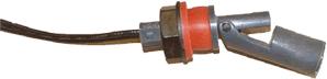
1. It depends on the signal from the solid state sensor, but my initial thoughts are yes, it should work fine. I can't really thinnk of any advantage of one type of sensor over the other.
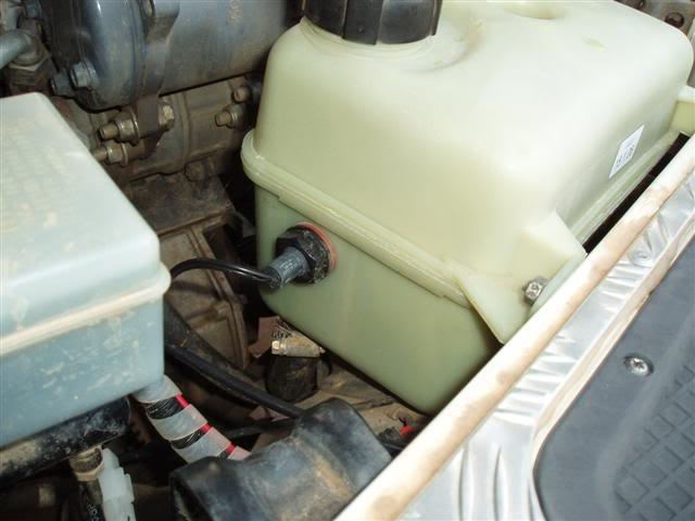
2. No, the top radiator hose will still have water flowing through it, even when the radiator is half empty. Think of the radiator as a tank being filled by your water pump (on the engine) via the top radiator hose. Or another way, imainge a fish aquarium with a filter pump running. You can have a full flow of coolant through the top hose when the engine is running but a low level in the radiator. The coolant flow will only be reflected in the top hose when the level has dropped so low that the pump begins to fail. However, if the engine was switched off, then yes, the low level would be reflected in the top hose too.
Paul
")


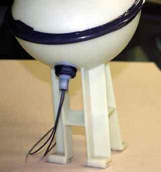

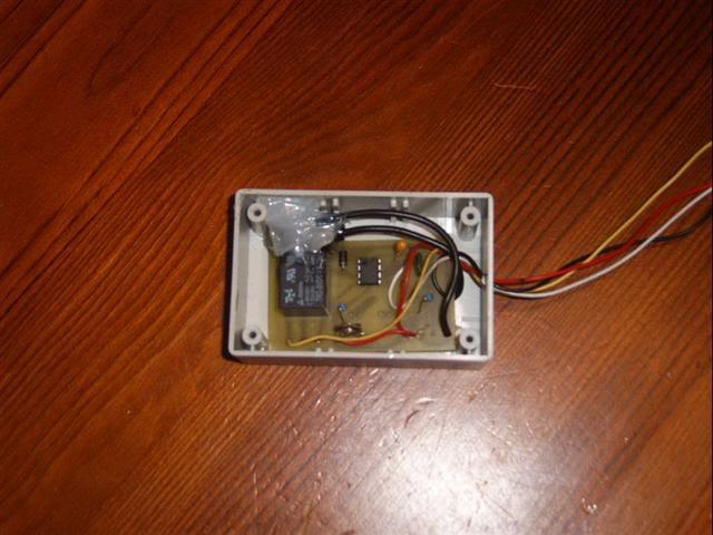
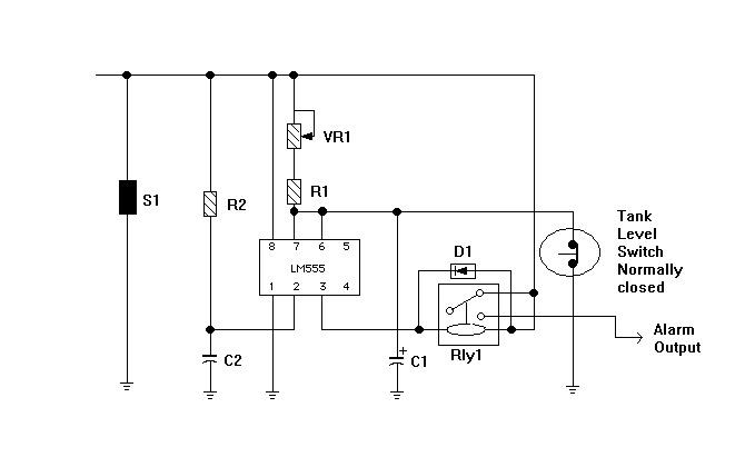
 This would inevitably lead to false alarms as the coolant sloshes around in the tank giving the sensor a hard time. Obviously what is needed is some sort of time delay. At this point my fellow Land Rover suffering mate, Pete, came to the fore. He put together a simple and robust little circuit from fairly commonly available components that achieves our objective i.e., a short (adjustable) delay before the alarm is triggered to prevent false signals when off road.
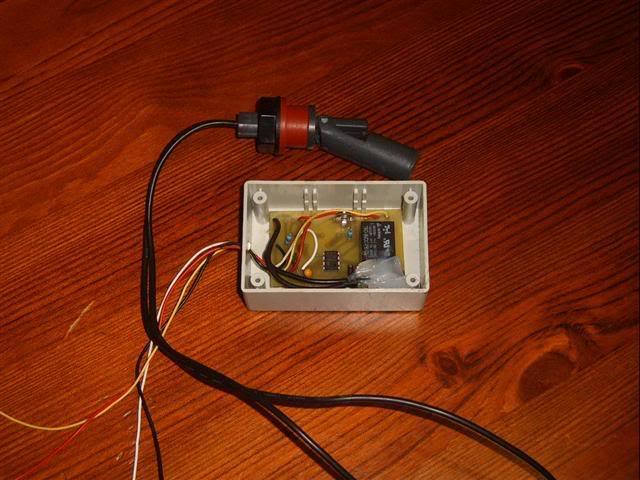


 Reply With Quote


 [/IMG]

")

Bookmarks