

 Reply With Quote
You are ?. erm?. ah, Well you're the cleverest Land Rover builder I think the internet has ever seen. I mean this build goes beyond?? ANYTHING.

Hi Stirling,
I'm just getting used to this forum, hopefully you got my last message?
Can you send me your email address?
This way I can share my maps with you.
In addition to my last message the best advise I can give is you absolutely must use a closed loop strategy, this is essential!!!
You will never get the engine running nicely over a mix of ambient temperatures on an open loop map, you will map it one day and it'll be perfect, then the ambient temps will change slightly on day two and it'll all be out again.
Closed loop with correct AFR targets is definitely the solution as is using LPG temperature & pressure compensation to assist it.
The volume of LPG goes up and down massively even over small temperature changes, and this has a big impact of your AFRs!
Cheers, Dave.
 Wizard
You are ?. erm?. ah, Well you're the cleverest Land Rover builder I think the internet has ever seen. I mean this build goes beyond?? ANYTHING.
Fossicker
I have to agree, just spent the last couple of days going through this build thread and your attention to detail is second to none.
Love the engine build and your sheer determination to get the project running, but not just throw it all together in the final stages, just to say it's finished.
Great job and it makes my build thread look rather lame in comparison !
Cheers Cookie
Master
SupporterOriginally Posted by mrapocalypse
 Wow, thanks for the complements apocalypse and cookie!
Ok with with progress!
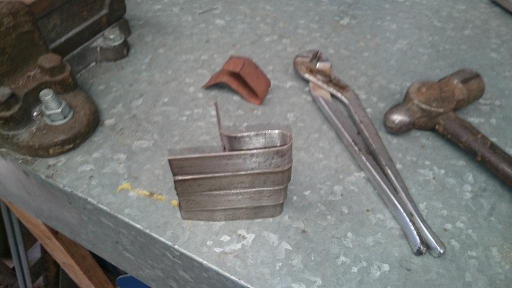
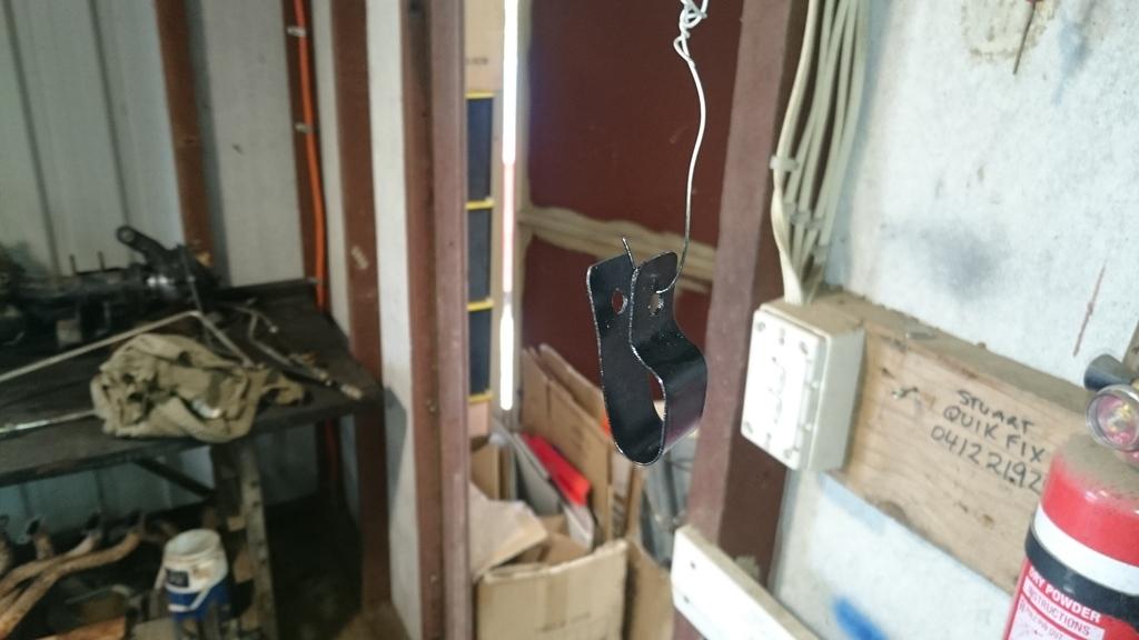
So, i've finally started getting into some aluminium welding. First up the LPG evaporator bracket.
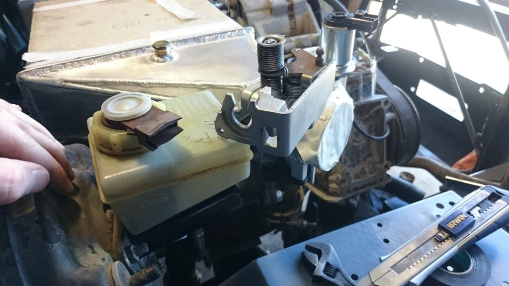
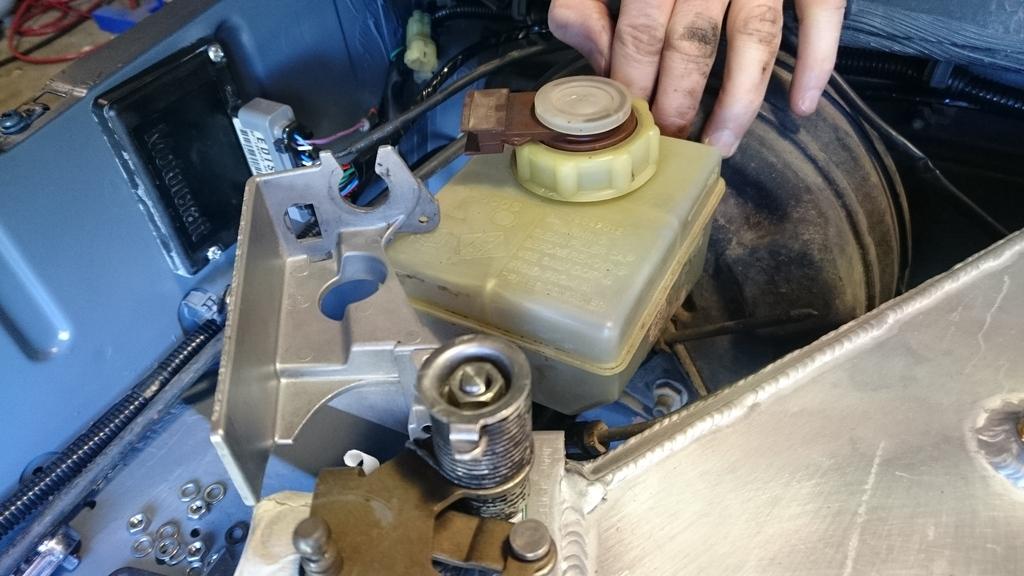
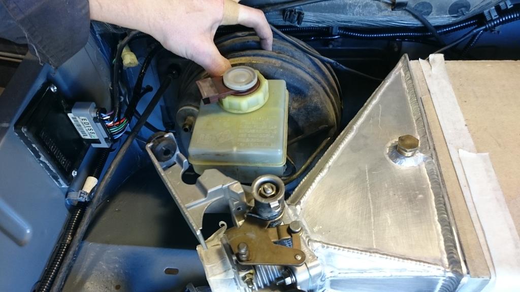
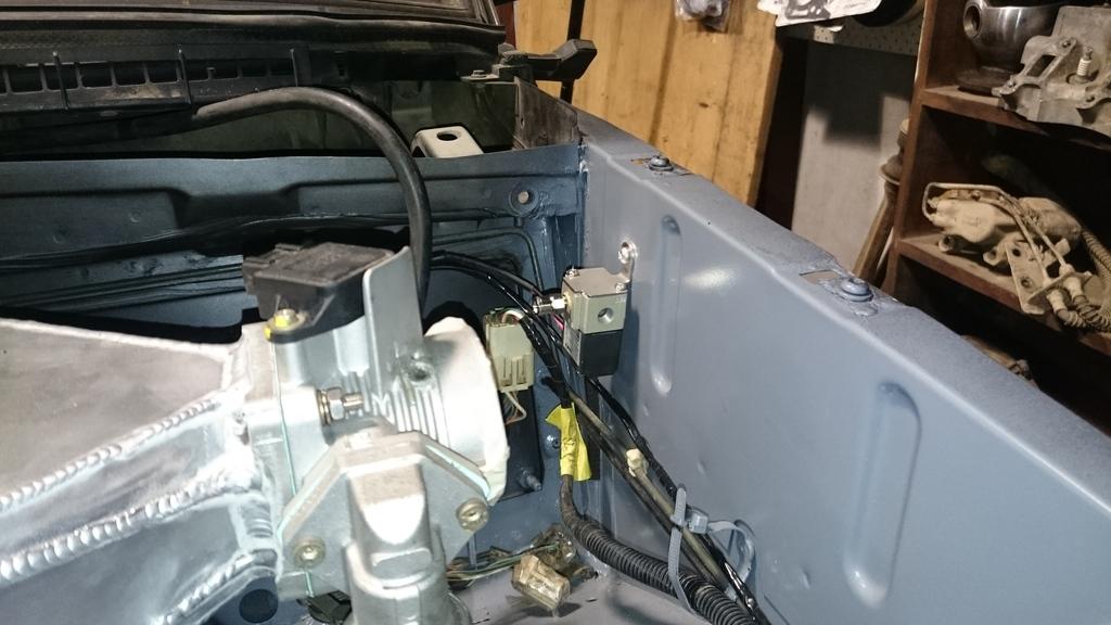
Then, i had to deal with my oversight of the fouling between the brake master and the RH throttle body.
I ended up needing to do some modifications to relocate the throttle cable. I haven't done the same change to the LH throttle body, so there will be a very slight difference in the movement of the two throttle bodies. I don't think it is enough to be concerned over.
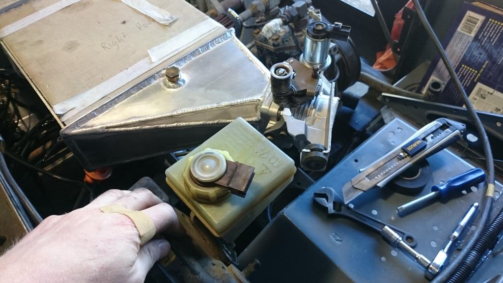
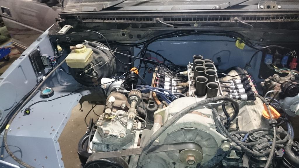
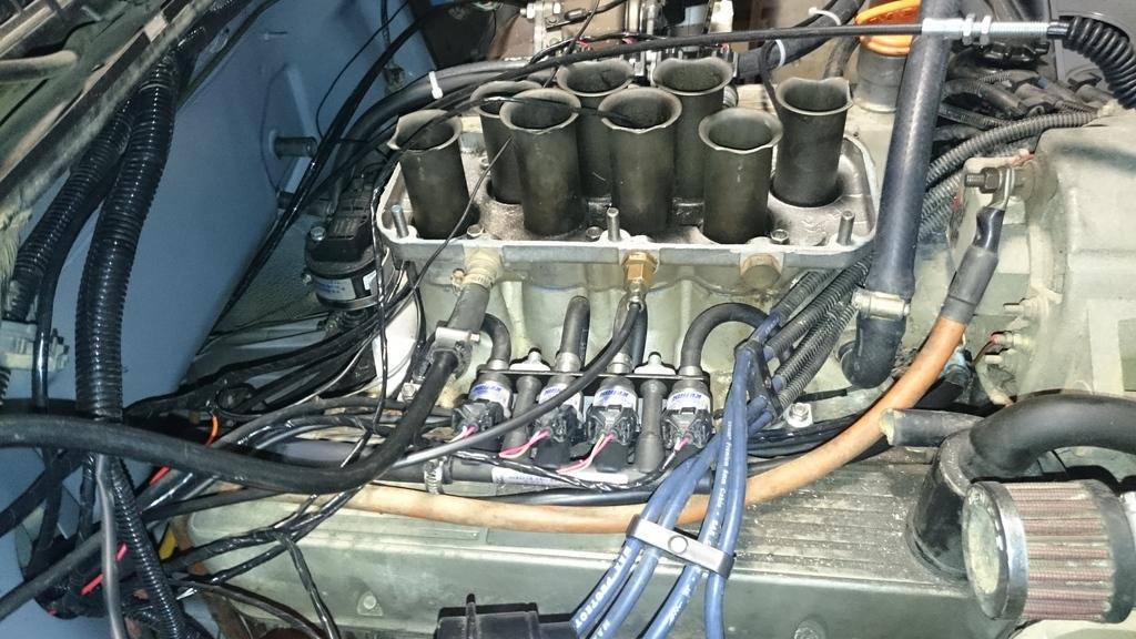
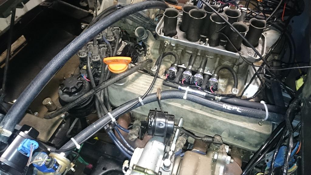
The shot below are just a general look over the engine bay.
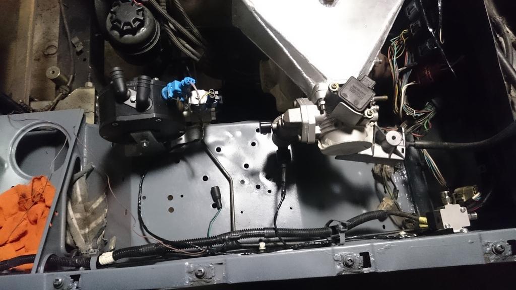
Some of the wiring i've been doing. The LPG evaporator solenoid, evaporator temperature, idle valve and boost control solenoid.
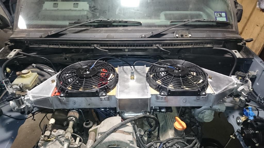
Some more aluminium welding, thermo fan mounting points.
And that's it! Next weekend I'm off on a holiday for a couple of weeks to iceland and germany. I'll try to squeeze in a couple more nights before leaving.
Stirling
Master
SupporterOK, so a few more days spent trying to keep progress moving!
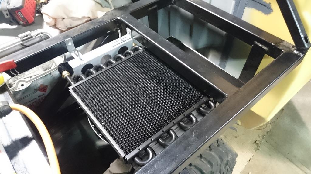
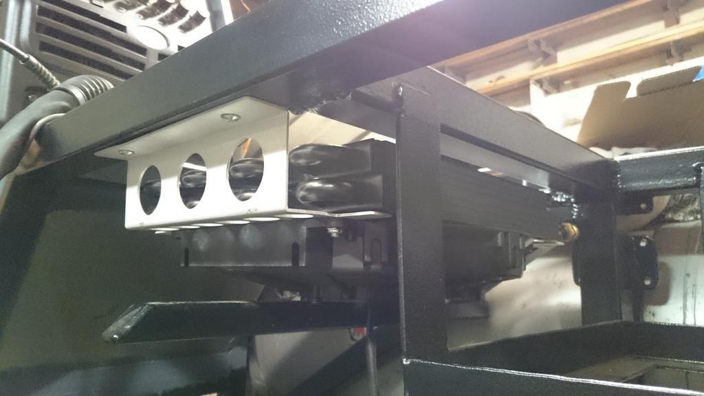
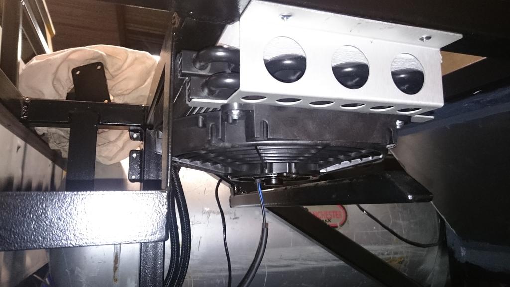
The oil cooler for the engine oil was mounted onto the tray:
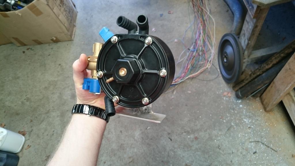
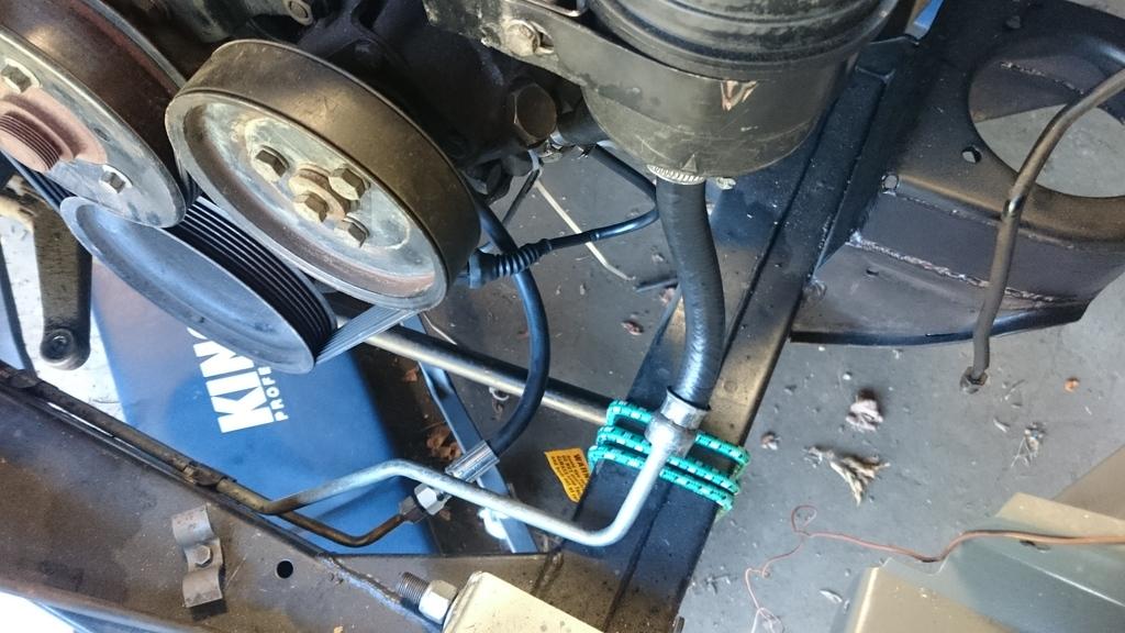
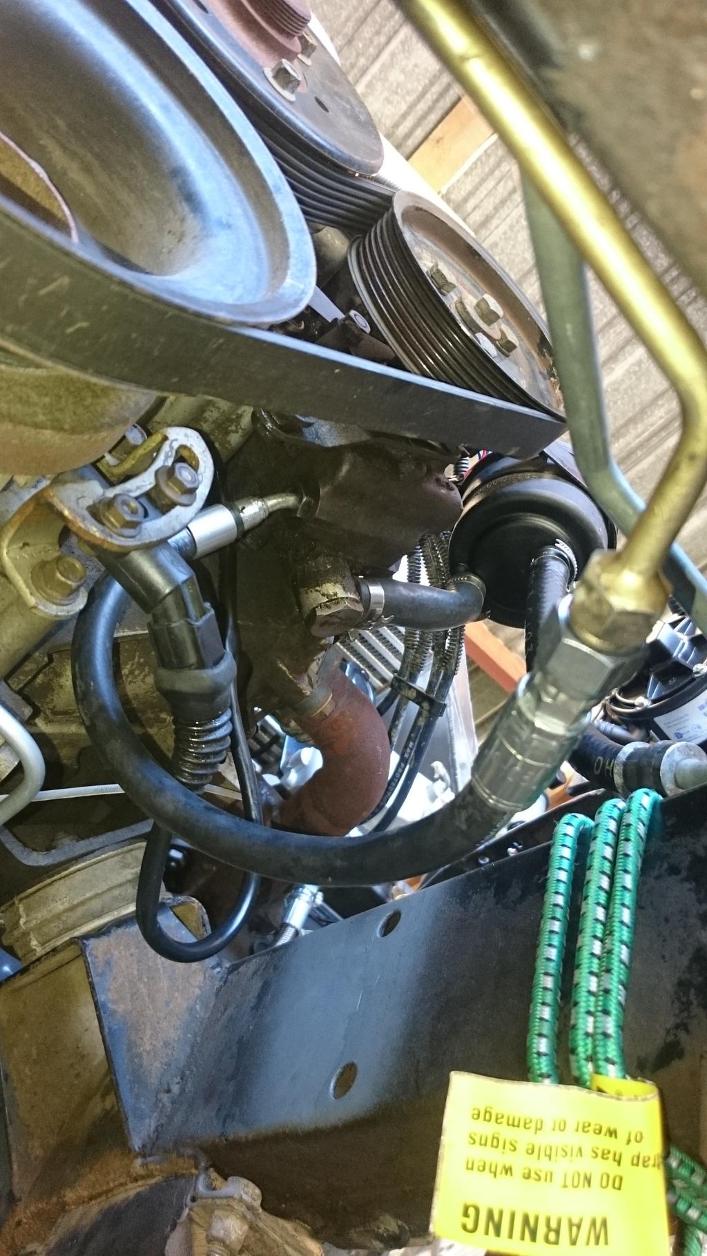
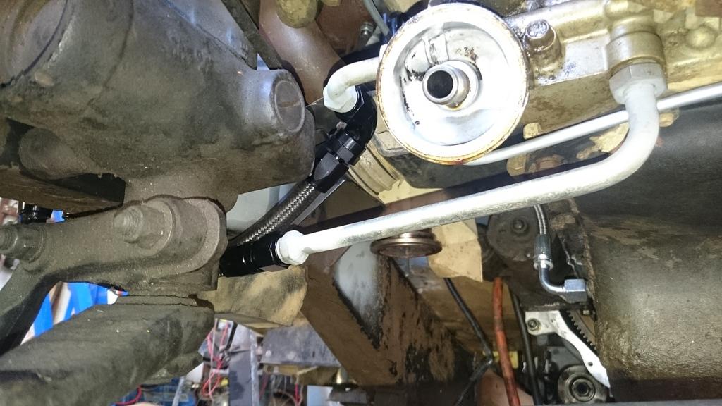
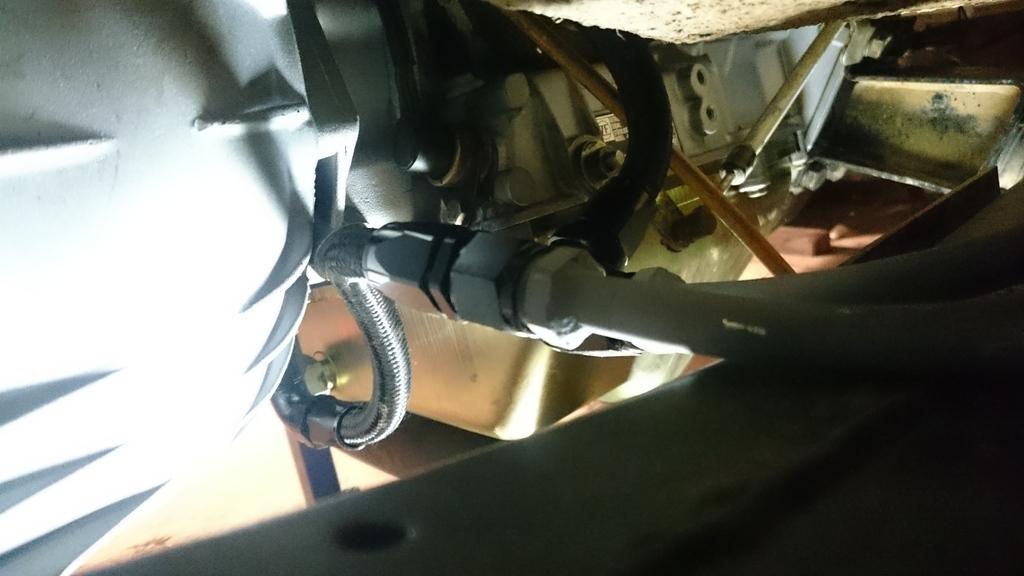
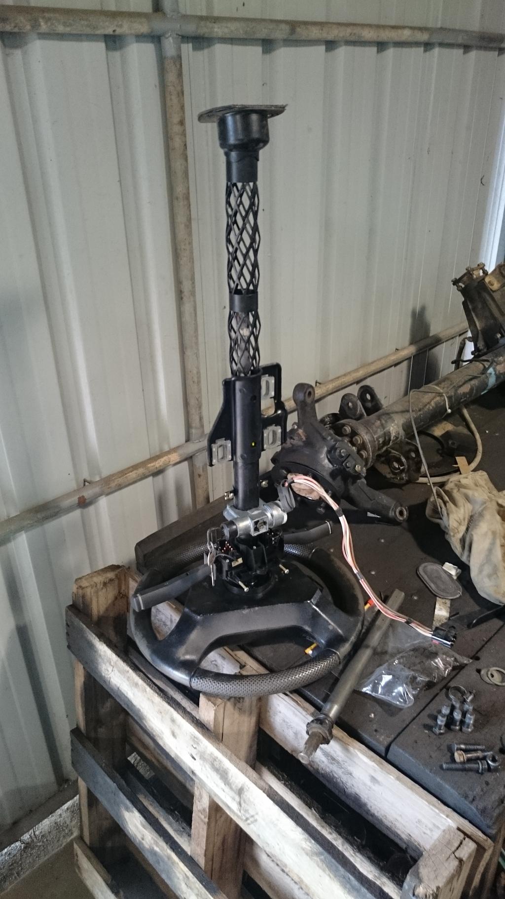
I got the pressure side of the power steering piping modified to make it suit the oil pump on the engine. Actually, does anybody recognize the power steering pump I have? Is it Land Rover? Because the guys at Pirtek said the fitting for it is an Air Conditioning Fitting?!? Also, I think I may have killed the bearings by running it dry for too long, so I probably need to source a replacement very soon! If anyone has any tips, let me know. Photos below:
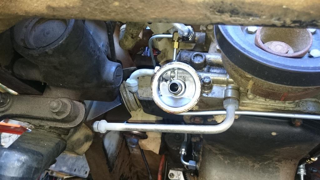
Here are the modified oil points to send the oil off to the oil cooler and for the return into the oil filter. I just cut and re-welded the pipes and welded some AN-8 fittings on:
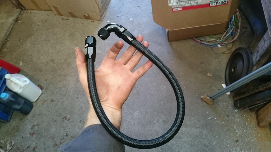
Getting started on making up some of the flexible hose, this one was to go between the oil cooler and temperature sensor:
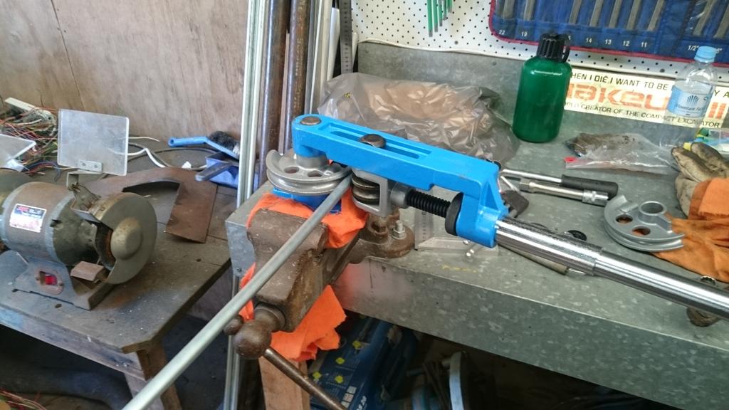
Putting my new pipe bender to use by bending up the pipe run from the engine all the way to the tray. I was ambitiously trying to do it in a single run:
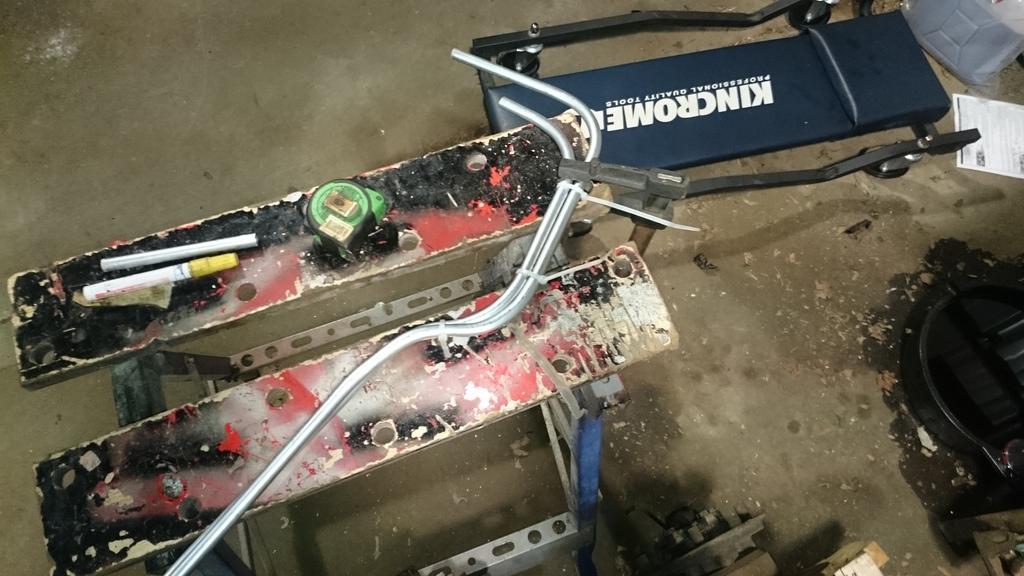
It was particularly tricky to bend up the pipe to stay neat and follow each other, but I got there in the end:
Making up some of the brackets from sheet steel to hold the pipes in their respective places on the chassis, nothing particularly special...:
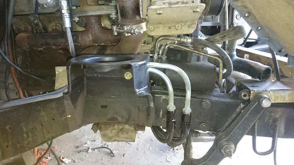
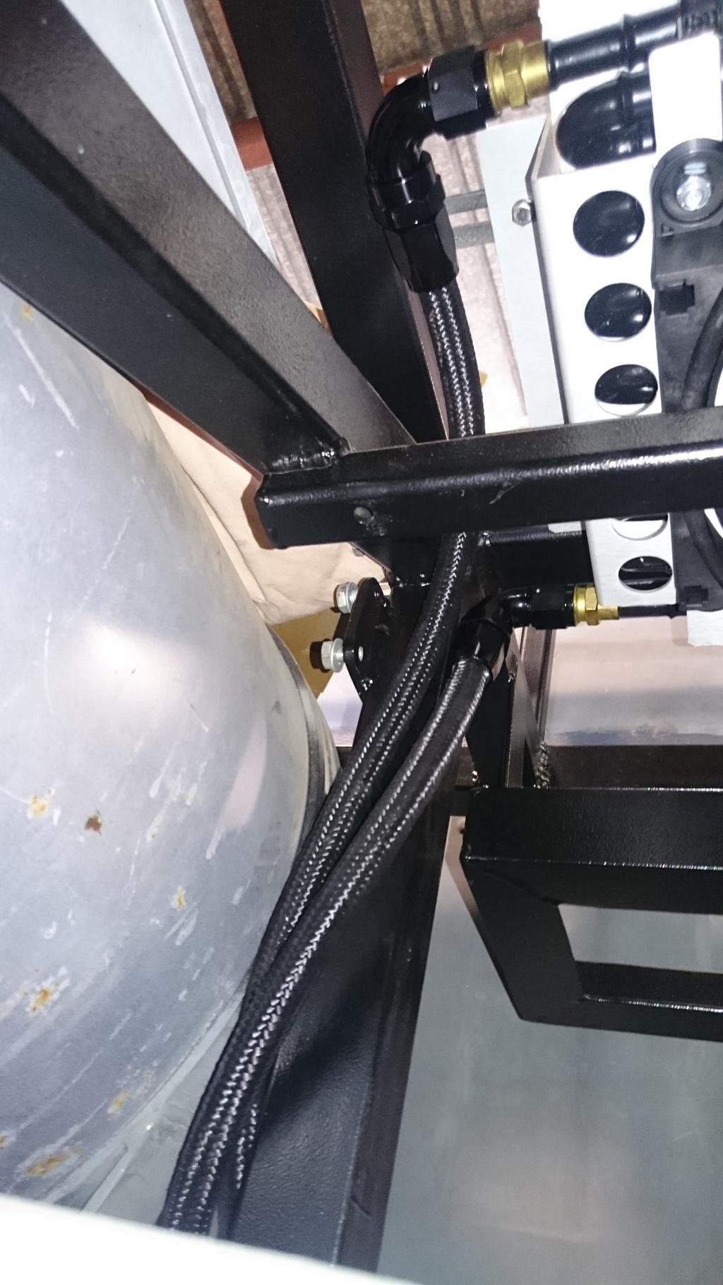
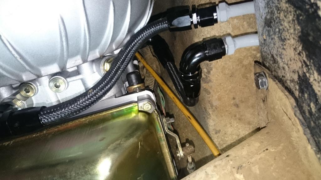
Here is what the finished product looks like. The flexible pipes running from the oil pump and to the oil filter, they are a bit tight for my liking, so I may need to redo them later. I'll need to see:
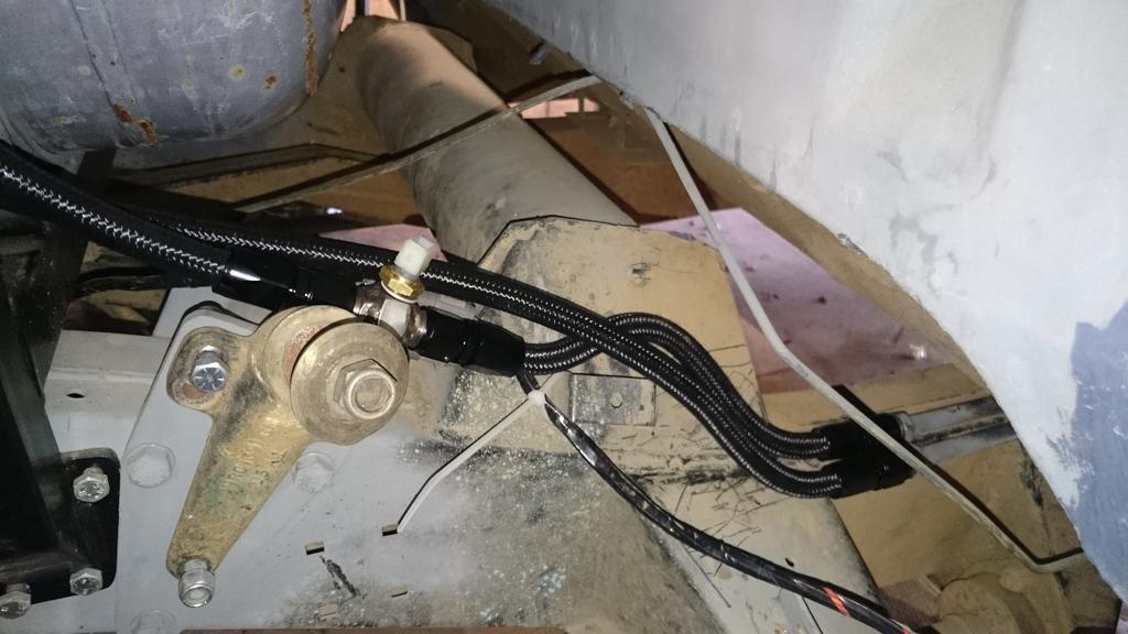
The mounting of the temperature sensor I made. I needed to weld on a piece of stainless steel so that it could be mounted. Anyway the steel pipes finish just under the cab, and then it is flexible pipes from there to the oil cooler:
Attachment to the oil cooler:
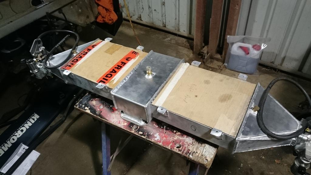
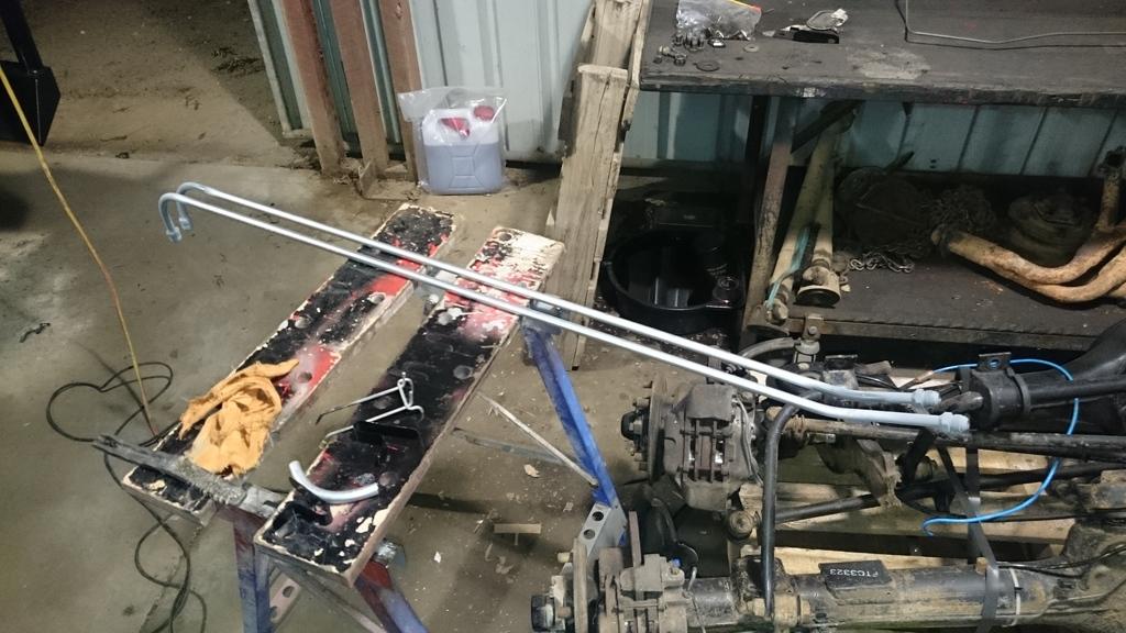
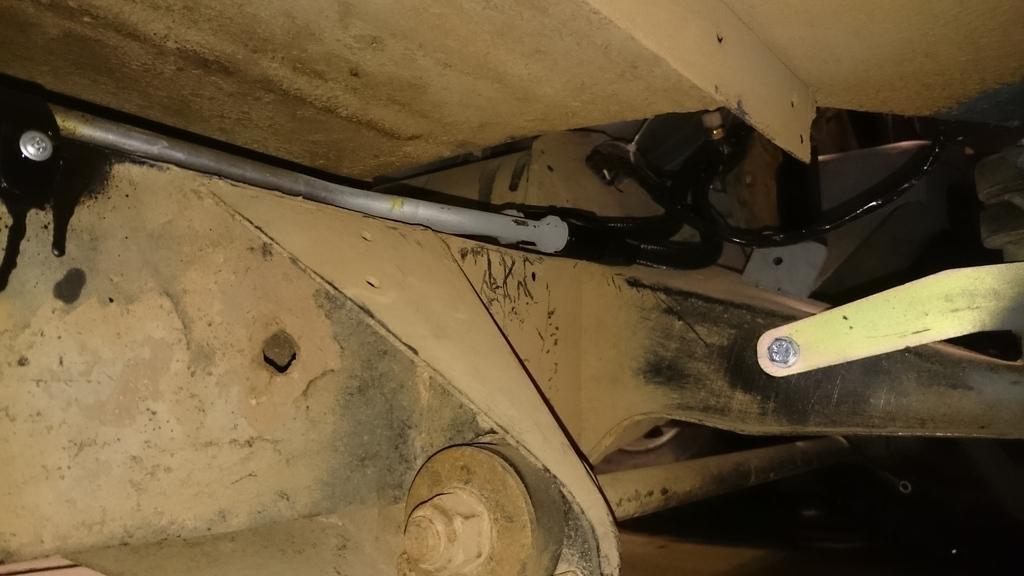
And here is the shot of the finished transmission oil pipes, my Girlfriend bent them up for me! The transmission oil cooler lines are way simpler than the engine oil lines, and ended up being far neater!:
And that's it for the update! Till next time.
Stirling
Wizard
Power steering pump
Hard to tell from the pic but your power steering pump looks like the Eaton one we gad on the rangie - they are fully rebuild able. Only ones that are.
Mob in bris rebuilt ours for lot less that cost of 'replacement' ones that are really throw away jobs.
These are good units so worth seeing if it is an Eaton.
Somewhere on the rangie ute build site there is a post and pictures re the rebuild.
Skiboy
89 Orange Rangie UTE - our play thing - sadly now sold
75 Rangie/Series/Hybrid/LS3 - Bumblebee with a sting!!!!
2018 RRS - The new touring vehicle - replaces 2012 RRS
Master
SupporterThanks for the info Skiboy, it's appreciated.
On to progress.
The automatic transmission oil cooler and oil lines were installed onto the car. I think i'lol need to use a protective plate on the return line on the bottom of the gearbox.
All the vacuum lines on the plenum were sorted, I drilled and tapped some threads to use push lock pneumatic fittings and 6mm pneumatic pipe. The 16mm LPG value line was fitted, I'll need to swap it out as it's coolant pipe and not rated for LPG. Just need to wait for the right pipe to arrive.
The ignition switch wasn't working (no contact) so that was pulled apart and sorted out.
I sorted out the cables and plugs to hook into the automatic and engine oil temperature sensors.
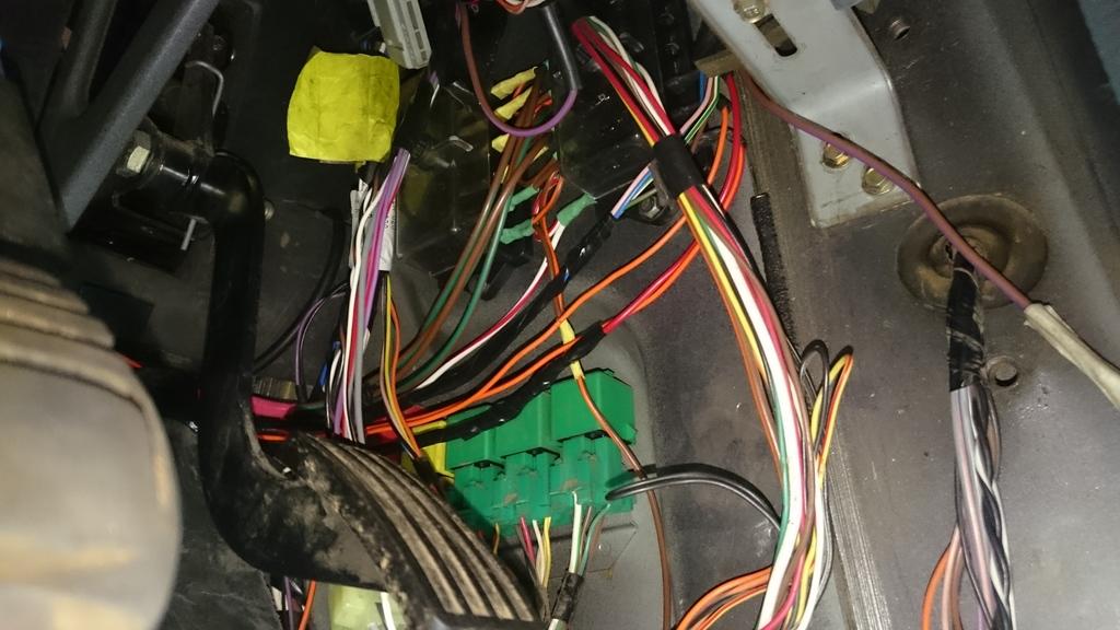
Finally, a good dent was made on the power supply wiring of the system, the main system relay and fuse boxes are now setup.
That's all folks.
Stirling
ChatterBox
Hey mate will you have a cover of sorts over those coolers? Won't they end up full of mud?
Wizard
Qu - are you putting anything around the pipes/hoses?
Long term you may have some abrading points ? maybe cabletie some water hose offcuts on key points?
The issue with custom design is there is no field testing tosee what happens over time - the more you can foresee the usage-over-timeeffects the better the design.
Also remember that you need access to service - so how hardis it to remove components once complete - often the assembly is done when youhave access that will not be there when fully assembled. eg the point made above re cleaning the coolers.
Skiboy
89 Orange Rangie UTE - our play thing - sadly now sold
75 Rangie/Series/Hybrid/LS3 - Bumblebee with a sting!!!!
2018 RRS - The new touring vehicle - replaces 2012 RRS
Master
SupporterHi Jock,
The oil coolers are pretty well protected, they sit above the mud guards and below the tray skin. I'll have a removable panel to gain access from the top.
Hi skiboy,
Abrasion will be a problem and I'll need to address that closer to the end, putting sleeves over the steel pipes will be a good way to go. I also need to put a bash plate over the transmission oil return line.
So progress - I have been in the workshop both this weekend and the previous weekend. But all I'm doing is boring wiring,
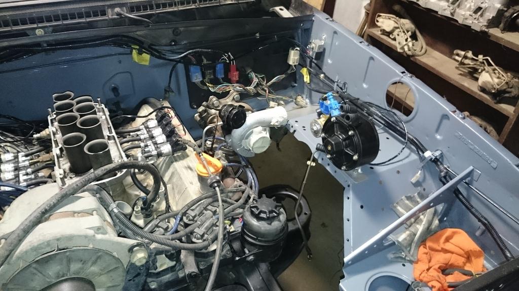
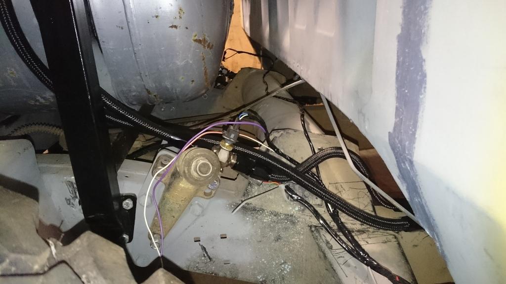
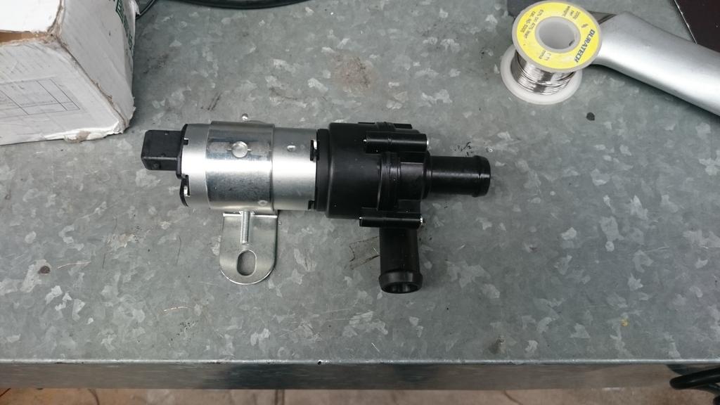
I was looking at how I was going to get the coolant to the turbos. I really wasn't comfortable using the heater circuit because it would mean very hot water would be delivered at the inlet of the engine water pump (and go through the engine). I really needed the turbos to be supplied with coolant from the outlet of the radiator and discharge into the inlet of the radiator. So... No choice but to go for an auxiliary coolant pump:
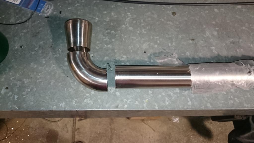
Also, my stainless steel parts arrived for me to weld up the tube run from the turbo outlets to the throttle body inlets. I need to get another gas regulator to be able to back purge the Inside of the pipe during welding:
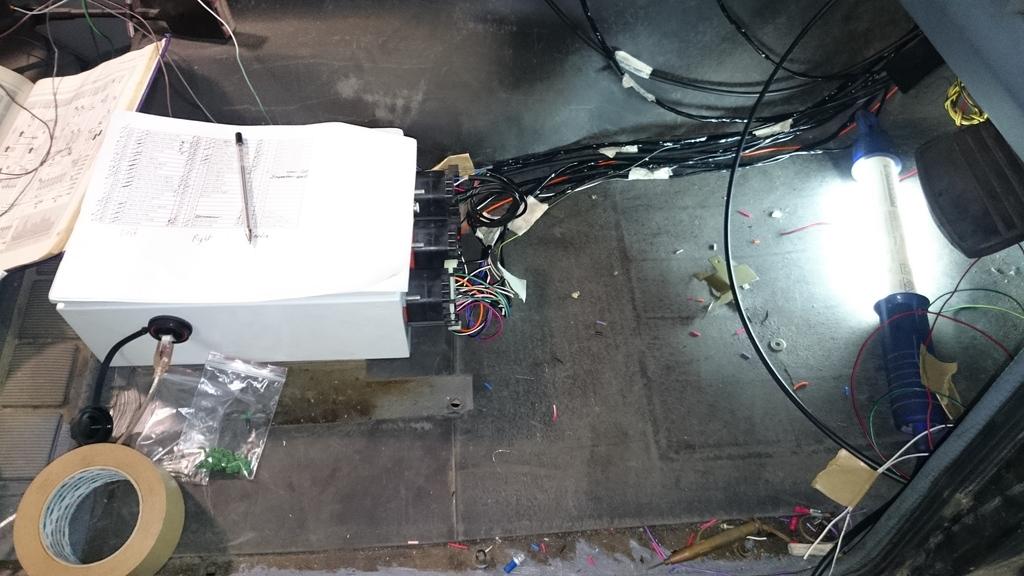
I've made a good dent on the wiring. I've got a temporary battery in and wired up to the starter motor and I can now crank the engine. Power is also to the dash as well and to the ECU. About 40% of the connections are now made, I'm testing that sensors work along the way. Also, the ECU is wired to give an oil pressure warning light and engine fault light which is great because they are programmable.
I'm not far away from being able to start the engine in the car!
Stirling
 Posting Permissions
| Search AULRO.com ONLY! |
Search All the Web! |
|---|
|
|
|

Bookmarks