Page 4 of 4 FirstFirst ... 234
Results 31 to 38 of 38

Thread: Diggers '52 80"

  1. #31
    Join Date
    Jan 1970
    Location
    under a rock, next to a tree, at Broadmarsh
    Posts
    6,738
    Total Downloaded
    0

    Water problems with the old Wee Beastie

    Quote Originally Posted by digger View Post
    OK, couple quick questions:

    *- part number for the correct waterpump? (im being lazy here I know)
    This one is easy, Item 1----Water pump assembly----- Part Number 241884 ---(The same number for both engines)
    *- best place (and price) to get said waterpump?
    Try Jim at Four wheel drives, Melbourne (Tell him Arthur sent you and he will say Who?)
    *- what else should I be looking at doing as I do this change over?
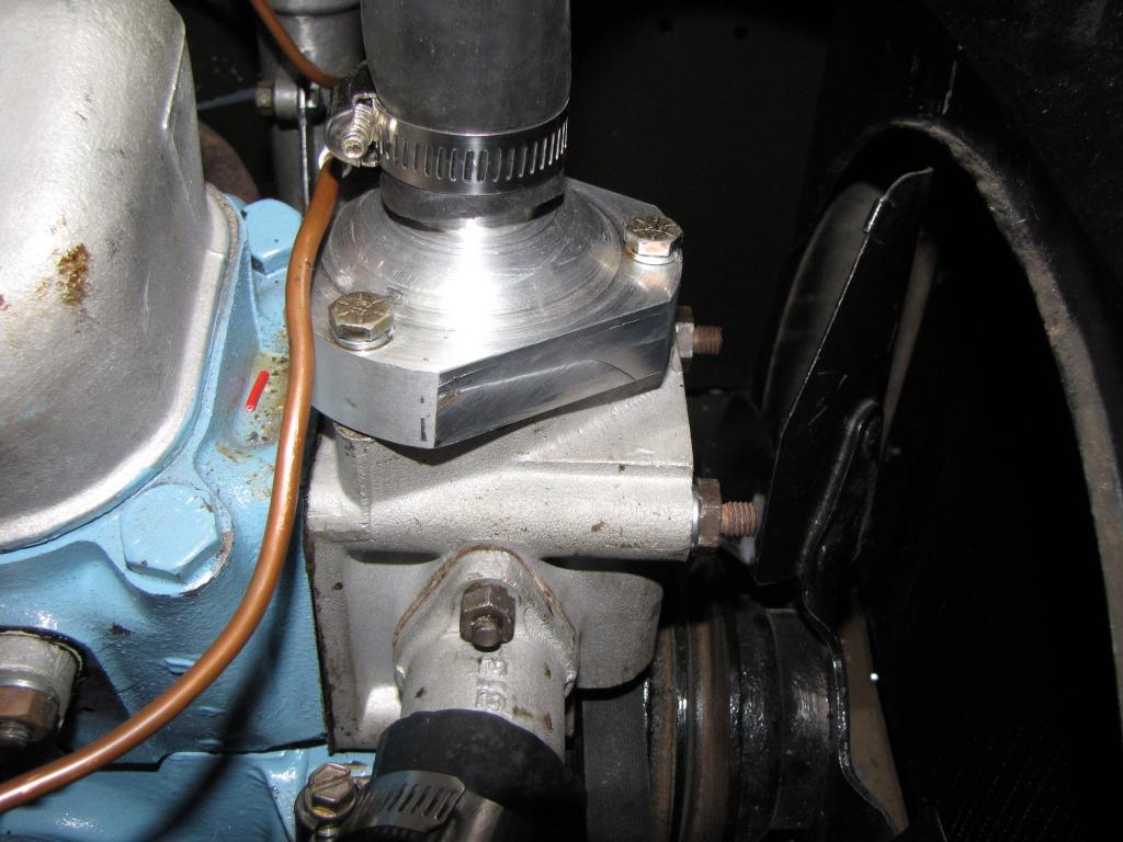
    Corrosion inside the alloy housing's, Item 19-----Thermostat housing ------ Part Number 263670.
    Item 31-----Water inlet elbow to thermostat-----Part Number----263630.
    Item 28-----Water outlet pipe, thermostat to radiator----Part Number---263607.
    Replace, Item 17-----Rubber joint ring, (connecting water pump to thermostat housing) -----Part Number----09170.
    Check, Item 18-----Copper tube, (connecting water pump to thermostat housing) -----Part Number----09197.

    *- I have removed the thermo housing bolts but it isnt budging at all, other than levering it up is there some other method to remove it?
    Bigger hammer
    will it come off with the water pump then try to twist the two to separate?
    cheers
    Digger, I have a reprint of the Parts Catalogue, Part Number 4051 for 1948-53 Series I models, now that means anyone that needs a few numbers can feel free to shoot me a question.
    .

  2. #32
    Join Date
    Aug 2007
    Location
    Loganlea Qld
    Posts
    1,652
    Total Downloaded
    0
    Digger, don't even attempt to remove the top part of the thermostat housing unless you know for a fact that the thermostat is US. The outlet pipe housing (see below) is attached to a "box" like (part #263670) and this housing is fixed to the front of the head by 3 long and one short studs. Remove this housing complete with the outlet pipe and inlet pipe bits still fitted. The whole housing assembly merely sits on top of a rubbery washer and copper tube to the water pump.
    The actual thermostat outlet pipe housing itself is a rather delicate piece of equipment made out of a reasonably soft aluminium foil-like material and prising it out with a screwdriver or the likes of such can do irreparable damage.


    I have just spent a couple of days re furbishing my thermostat housing using a "dremmel" and some "quik-steel", (an epoxy two pack synthetic metal mix available from most car outlets- similar products have different names) to rebuild the eroded away shelf upon which the actual thermostat sits inside the housing, and also had an acquaintance from the MJCQ turn me up a new outlet pipe section as per the photo below.


    Take note that the seal around the thermostat is actually between the internal "shelf" inside the housing, the thermostat itself and the bottom of the collar of the outlet pipe housing, not between the outlet pipe housing and the thermostat housing.
    There are only the three openings to this housing, the small inlet hole from the water pump itself at the bottom, and the two inlet/outlet pipes unless your was fitted with a heater. There are two other outlets but both of mine are blanked off. The face that is sitting against the front of the head, even though there is an outlet from the head itself, is sealed off and does not allow water ingress.
    Hope that this of some use to you.
    Regards
    Glen

    1962 P5 3 Ltr Coupe (Gwennie)
    1963 2a gunbuggy 112-722 (Onslow) ex 6 RAR
    1964 2a 88" SWB 113 251 (Daisy) ex JTC

    REMLR 226

  3. #33
    Join Date
    Sep 2007
    Location
    RIVERLAND, SOUTH AUSTRALIA
    Posts
    6,740
    Total Downloaded
    0
    Cheers guys!


    More questions..

    I also need the metal flexible tube the wiring travels in up to the windscreen...
    **do they still make it?
    **If not, where would anyone suggest I look for some?

    Now while I'm at it, I have a pair of nos (still in wax paper sealed boxes) trafficators, I want to put them on the windscreen BUT also run a set of led blinkers front and back...

    I need 12V CONSTANT to trafficators
    I need 12V to flasher can so alternating power to operate LED front and back(eg blink)

    My question is this...

    can it be done off the one switch? (i think so)

    I assume two sets of wires from blinker arm 'blade"(instead of the usual one), that being 1 to trafficators , and another to flasher can and onwards, BUT will this:-

    ** overload the switch?
    thinking standard (replica with hazards switch) magnatec style indicator arm OR (I prefer) bakelite (old style) switch in centre of windscreen..

    **So, if going via bakelite switch how can I get front and rear LEDs to flash as hazards? (I assume another switch...?)

    Interested in wiring designs - step by step if needed!!
    But set out for a pinhead like myself to understand please...

    Photos if someone has done it?

    The trafficators are held open and lit by the constant power they cannot have too much variation as I understand it as they'll close/open/close open etc etc until buggered!!

    I hope thats clear.... (probably like mud! )
    ask if there is more info needed...
    Cheers
    (REMLR 235/MVCA 9) 80" -'49.(RUST), -'50 & '52. (53-parts) 88" -57 s1, -'63 -s2a -GS x 2-"Horrie"-112-769, "Vet"-112-429(-Vietnam-PRE 1ATF '65) ('66, s2a-as UN CIVPOL), Hans '73- s3 109" '56 s1 x2 77- s3 van (gone)& '12- 110

  4. #34
    Join Date
    Jan 1970
    Location
    under a rock, next to a tree, at Broadmarsh
    Posts
    6,738
    Total Downloaded
    0

    wiring tip bits for a wee beastie

    Hi Digger

    To get the wiring size right use this guide.
    Autosparks, World leading supplier of classic car wiring looms

    wiring diagram for the indicators.
    Land Rover FAQ - Repair & Maintenance - Series - Electrical - Reference - SI Wiring Diagrams

    key to wiring diagram
    Land Rover FAQ - Repair & Maintenance - Series - Electrical - Reference - SI Wiring Diagrams

    wiring diagram for the 51,52 and 53, without trafficators
    Land Rover FAQ - Repair & Maintenance - Series - Electrical - Reference - SI Wiring Diagrams

    to divert the current away from the switch, a couple of automotive relays can be wired to operate the trafficators with the indicator switch.

    Important! 
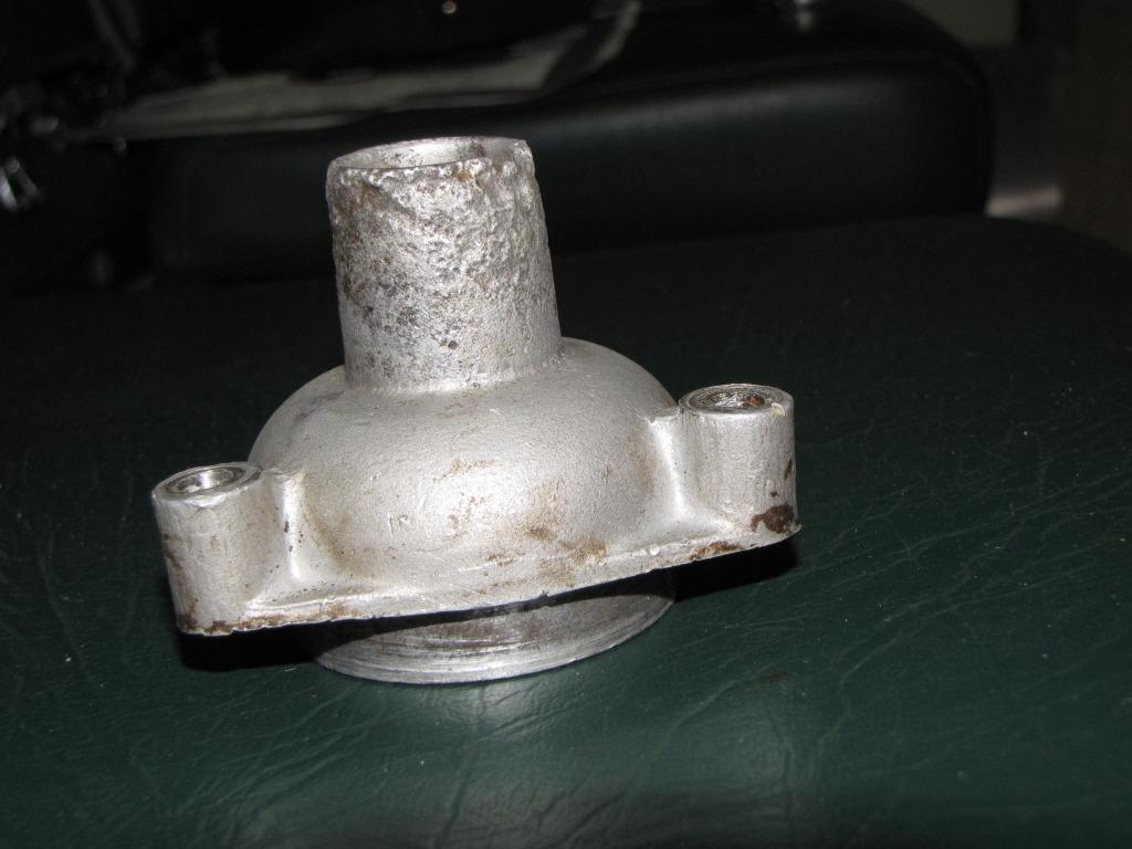
always use a fuse at the point where any power is picked up from.

    this is a schematic of a four way flasher adapter for a negative earth system, ( early Land Rovers are positive earth unless converted to run a radio, etc ).
    http://www.lrfaq.org/images/4way_ver2.jpg


    ref; http://www.lrsoc.com/forum/index.php'topic=7274.20

    These are the units destined for the wings, L489 lenses I think, with L488 double filament bulb holders.

    Last edited by wrinklearthur; 1st September 2012 at 05:35 AM. Reason: add a photo and words

  5. #35
    Join Date
    Dec 2006
    Location
    Narrogin WA
    Posts
    3,092
    Total Downloaded
    0
    There are cast-iron water pumps available on Ebay, which don't fit perfectly and require a bit of grinding and a thread change - quite cheap though and better than a corroded one,

    Cheers Charlie

  6. #36
    Join Date
    Sep 2008
    Location
    smurf village
    Posts
    8,332
    Total Downloaded
    0
    how much are the cast iron ones i have seen some on there for $150 and some for $230

  7. #37
    Join Date
    Jun 2009
    Location
    Queensland
    Posts
    3,434
    Total Downloaded
    0
    Quote Originally Posted by schmierer LR at singleton View Post
    how much are the cast iron ones i have seen some on there for $150 and some for $230
    Last one I bought was from the 4wd mob in Vic. $175. One hole needed opening with afile but its still working OK. No complaints yet.

  8. #38
    Join Date
    Oct 2007
    Location
    Red Cliffs
    Posts
    295
    Total Downloaded
    0
    Quote Originally Posted by zulu Delta 534 View Post
    There are only the three openings to this housing, the small inlet hole from the water pump itself at the bottom, and the two inlet/outlet pipes unless your was fitted with a heater. There are two other outlets but both of mine are blanked off. The face that is sitting against the front of the head, even though there is an outlet from the head itself, is sealed off and does not allow water ingress.
    Hope that this of some use to you.
    Regards
    Glen
    There is in fact 4 openings, there is a very small hole about 1/8" in the back of the housing into the head. This is a bleed hole and is often corroded over.
    I find if you use 2 nuts on each of the retaining studs that hold down the top outlet to remove them completely the top will come off without too much damage as the thermostat generally needs changing.
    Dennis

Page 4 of 4 FirstFirst ... 234

Bookmarks

Bookmarks

Posting Permissions

  • You may not post new threads
  • You may not post replies
  • You may not post attachments
  • You may not edit your posts
  •  
Search AULRO.com ONLY!
Search All the Web!