


 Reply With Quote
more pics:


 ForumSage
Hey all,
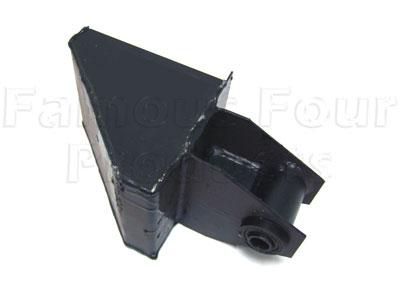
I have had this idea for ages but for a few hurdles I havent done anything about it...I would like to increase the length of my rear trailing arms. The rear cab outrigger on my Def 110 CC is approx 250mm forward of the trailing arm mount. So I want to remove both the TA mount and the Body out rigger and fab a new one for both.
I have done a quick carboard mock up of the concept. The main body im thinking 3mm plate. Top and sides and end all one peice folded. There will be atleast one internal web and a bottom with, either dimple holes or holes with right angle banding.
Any thoughts, ideas and comments are welcome

Last edited by uninformed; 9th January 2017 at 07:10 PM.
ForumSage
more pics:
Last edited by uninformed; 9th January 2017 at 07:09 PM.
Swaggie
For yours I wouldn't have made it cover the top of bottom plates of the chassis rails for cracking and complience reasons. I would also have changed the chassis mount to a Nissan Patrol rear link bush pattern - I think its a better arrangement
I would have just adapted a Series LWB rear spring mount by removing the spring mount on it and refabricating a Patrol type on the face of it. Then weld it on to the side of the chassis making sure it contacts the top and bottom plates.
Cheers
Slunnie
~ Discovery II Td5 ~ Discovery 3dr V8 ~ Series IIa 6cyl ute ~ Series II V8 ute ~
ForumSage
All im doing is duplicating what LR have done top and bottom on both the TA mount and the outrigger. Personally I think it very sound design. I feel that the way the bottom of the TA mount locates to the inside corner of the chassis rail much better than just the outside...
Swaggie
Sorry, I missed the outrigger being a body mount also.
Complience.... meaning engineer approvable.
Cheers
Slunnie
~ Discovery II Td5 ~ Discovery 3dr V8 ~ Series IIa 6cyl ute ~ Series II V8 ute ~
ChatterBox
SupporterI have been looking at doing exactly the same thing.... have you seen the gigglepin rear arms? i know they remove the standard mount and put a new one on further forward, i havnt seen any pics of how they do it exactly but its something i have wanted to do for some time and have been thinking of doing something almost identical to your drawing or doing similar but using square tube with a mount for a large bush similar to patrol or land cruiser...
I just bought a 93 defender with the intention of turning it into a comp truck so i will probably have a crack at making some for that first before giving it a go on my county
ForumSage
Don't you swear at me!!!!Originally Posted by Slunnie

This being one of the hurdles....and I guess your concern is welding across the top and bottom flanges of the chassis rail. LR seem to have done it with success. If you look at the top that overlaps, the ends will be cut at an angle so the are not directly perpendicular to the flange. I'm even open to the idea of bending the lower piece that crosses the bottom flange, again so its not a direct 90 degree weld across the chassis.
Swaggie
Welding the top and bottom of the chassis is a little like wheel spacers. The manufacturer is allowed to fit them, but nobody else is subsequently.
Cheers
Slunnie
~ Discovery II Td5 ~ Discovery 3dr V8 ~ Series IIa 6cyl ute ~ Series II V8 ute ~
Master
SubscriberMake the mount on a folded c section to spread the load to wherever engineers need it
Gives options for plug and stitch joins
I'll have 2 please!
Dc
On a side note bill used to make complete bolt on kits to turn leafers
Into coilers
That's clamps around the rails for all mounts!
ForumSage
Here you go Cal:
[ame=http://www.youtube.com/watch?v=FT9Rt2s4wNE]Gigglepin car 4x4 - YouTube[/ame]
Not sure what all the froth on the patrol chassis end bush is about. Ill have to look at my neighbours when he gets home.....
There is definitely more than one way to skin a cat.......I guess what I am trying to achieve is a factory look
Im very aware of the legalities and lets remember it changes from state to state, and who you are dealing with. Lets just leave it at that and when the time comes IF it happens I will pass on all/any info to help others do this sort of thing by the books.
Im more interested in the engineering, ie design and strength....
What I like about the factory TA mount is that, to me, I visualise the arm pushing (due to axle housing rotation) now the mount is in compression, this why it has folds and is double layered for most part (3mm+4mm to create 7mm thick in sections) So the angle section that comes off the mount up to the corner and top of the chassis rail is stoping the bracket folding off AND transmitting force along the chassis...BUT, if this was all there was the chassis would also be being loaded inward....the small section that goes under the bottom and is welded along the bottom inside corner is also transmitting thr force, and Im thinking somewhat balancing out the inward force of the mount....basicly its a more forward push on the chassis than just a mount mounted to the outside
BTW, Im not building a comp truck, I dont need to tuck this all up above the chassis rail.
 Posting Permissions
| Search AULRO.com ONLY! |
Search All the Web! |
|---|
|
|
|


")
Bookmarks