

 Reply With Quote
while the MD actuator block was the place of failure, is it fair to say it was the cause.
Think about the definition of cause.....

 Swaggie
Similar failures can occur after buttressing a bone fracture such as a humerus or femur IF the buttress plate is not removed after fracture has healed. I had mine removed after 12 months for this reason. Like steel tubes bone is flexible. Further fractures will occur either side of the stiffened section if uneven forces are applied across/ along the length of the member.
The Cast centre of the salisbury differential where the axle tube enters is a stress/ failure point when load excedes the design strength
JC
The Isuzu 110. Solid and as dependable as a rock, coming soon with auto box😊
The Range Rover L322 4.4.TTDV8 ....probably won't bother with the remap..😈
ForumSage
while the MD actuator block was the place of failure, is it fair to say it was the cause.
Think about the definition of cause.....
Swaggie
I have a SIII Sals I cut open and posted the wall thickness on here. From memory it was 5.8 mm.Originally Posted by steveG

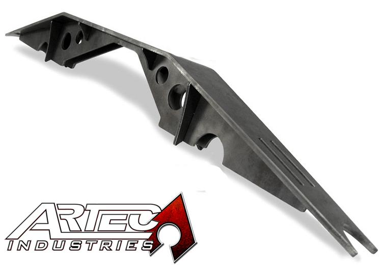
There are plenty of braces or stiffeners available for Dana 60s (which are basically the same axle). Buying or designing one that won't foul the suspension or fuel tank on a 110 is a bit more of an issue.
e.g. (not endorsing this one, just an example)
Caused no, however contributed to may be fair. Every non-MD sals I have seen fail failed where the tube goes into the centre. Every MD-equipped sals has failed at the actuator block (bearing in mind that is only 2 - Red October's 110 and the one on JRTs website).
I recall the MD installation instructions for a sals locker were explicit about making sure the hole in the housing had rounded corners and the actuator block welded on in short runs using a cold weld. Which suggests they were at least aware of the possibility.
Swaggie
Very true, it is all about the flex/ load cycles at stress raisers, causing crack propagation and then failure
jc
The Isuzu 110. Solid and as dependable as a rock, coming soon with auto box😊
The Range Rover L322 4.4.TTDV8 ....probably won't bother with the remap..😈
ForumSage
apparently the 110's fitted with load levelers were a bit more prone to bending and failure....mind you Id say 99% of all this comes from overloading.
Ben, another thing to have to design the truss around is the A frame mount and ball joint...
Swaggie
That is part of the suspension isn't it")
Master
Looking at the registration (North West Province South Africa) and the vegetation (mopani) I'd say this is somewhere in Southern Africa around the tropic of Capricorn.
A pot-hole would be the culprit.
An axle brace could have helped, but considering the depth of some pot-holes in Africa, maybe not.........
YarnMaster
Fatigue failure at the stress raiser caused by the abrupt change in stiffness from the thin walled axle tube into the cast housing.
IMHO nothing to do with the plug weld.
IMHO for carrying heavy loads, long distances over rough roads, they should have used a heavier wall thickness for the axle tube.
AT REST
In the red 110 it sure looks like the tube has just pulled out of the cast centre, maybe it had not been plug welded.
I have seen Series 3s where a full weld had been added around the joint and would be very wary of that as a solution - more likely to fail because of the weld there.
Bob
TopicToaster
SubscriberLooking at the photo of the center housing showing the opening where the tube has pulled out, the remainder of the tube is still inside.
To me it doesn't look like it has failed where it enters the housing, but that the crack has initiated from the outboard edge of the plug weld.
Am I missing something?
Steve
1985 County - Isuzu 4bd1 with HX30W turbo, LT95, 255/85-16 KM2's
1988 120 with rust and potential
1999 300tdi 130 single cab - "stock as bro"
2003 D2a Td5 - the boss's daily drive
 Posting Permissions
| Search AULRO.com ONLY! |
Search All the Web! |
|---|
|
|
|


Bookmarks