Page 3 of 6 FirstFirst 12345 ... LastLast
Results 21 to 30 of 51

Thread: Portals

  1. #21
    Join Date
    Jan 1970
    Location
    'The Creek' Captain Creek, QLD
    Posts
    3,724
    Total Downloaded
    0
    Quote Originally Posted by Bush65 View Post
    ...

    I couldn't tell from where I am, what was going on, but clearly something wasn't right. I suspect a lack of resilience coupled with stress raisers, and possibly not the best material choice.

    ...
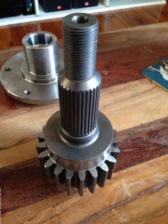
    Now that I have seen this photograph the problem is very obvious - as highlighted in the above quote.


    The splines look (from where I am) like they are rolled, not cut, which is good. However they finish close to a shoulder, which is bad.

    The pics don't show the important end of the hub, nor where the end of the hub finishes relative to the end of the spline and the shoulder. Both of those are important details when considering the stress raisers.

    Splines are bad stress raisers, but their affect can be reduced with appropriated detailing. Rolling is more beneficial than cutting. If cut they should have a long run-out. By far the best option is to increase the diameter where the spline is so the root diameter of the spline is much more than the diameter of the shaft and in conjunction use a very large transition radius (you will see this kind of detail in many torsion bars used in some vehicle suspensions).

    Steps in shaft diameter are bad stress raisers and the larger the size difference the greater the stress concentration. Using a large fillet radius reduces the stress concentration. Note that there are two steps in the diameter, one step up to the seal journal and another to the gear hub. The step to the gear hub is a large, and the intermediate step up to the seal journal will go some way to reducing the stress concentration that would have occurred if it wasn't present.

    When a component such as a bearing or hub is fitted on a shaft, it will be a stress raiser. This is why I mentioned the fitting of the splined hub before - the amount of stress concentration depends upon a number of details.

    When there are more that one stress raiser within close proximity their affects are compounded. As the separation distance increases the compound affect reduces and can be dismissed when the distance exceeds about one shaft diameter.

    In this case we have several stress raisers, a spline, two shoulders, and a fitted hub, in close proximity, such that the stress concentration from each will increase the overall stress and reduce the fatigue strength of the shaft.

    Attention to detail for reducing stress concentration is very important when designing components that are subject to fatigue. That is components subjected to fluctuating, cyclic or repeated load events. Loads that reverse direction are worse than those applied in one direction.

    Fatigue strength/life is complex, but is characterised by failure after a number of load cycles each of which are less than the static strength of the component. Each load application resulting in a stress magnitude above the Endurance Strength (BTW only possessed by steels) causes damage which accumulates (called cumulative damage - see Miner's Rule).

    Stress raisers have little affect on components under static loads.

    When evaluating fatigue strength, we reduce the static strength of the component using reduction factors that account for the stress raisers (which cause stress concentration), but also the material strength, and the size of the component. Greater reduction factors must be used for higher strength steels, and for larger diameter components.

    BTW the Australian Standard for design of rotating shafts (sorry can't recall the AS number (1410 rings a bell)) is only applicable for tensile strength less than 900MPa, which seems to be related to the difficulty of evaluating a reliable/appropriate reduction factor for material strength over 900MPa.

    The reduction factor for diameter is due to the affect of heat treatment on larger components.

    So we have here a stub shaft that has stress raisers that I have pointed out. These come before designers regularly, nowhere near as frequent as design for static loads, but every mechanical design engineer knows about them. Applied correctly, the design process should have ensured a shaft diameter that will give an appropriate finite life, if not an infinite life (stress needs to be below the endurance strength to achieve infinite life).

    My opinion is that proper consideration has not been given for shock/impact loads that occur in much four wheel driving. Designing for shock or impact loads is not an every day process, far from it, and many don't naturally anticipate it or are familiar with how to design for it.

    In this case one of the most important design details is resilience the ability to absorb impact energy by transforming it into strain energy, without exceeding the allowable stress. The amount of strain energy is a function of the distribution of stress over the volume of material. If you have a small volume of material the stress will be higher for the equivalent strain energy.

    BTW I should have pointed out that there is a direct relation between stress and strain. Modulus of Elasticity (E is approximately constant for all steels) = Stress divided by Strain, which can be rearranged to Stress = E x Strain.

    I will bet my bottom dollar that the failure occurred because the shaft lacks enough resilience, thus very high stresses were concentrated in the area at the end of the splines. It wouldn't have necessarily had to fail during a shock load application, but any and all shock loads during its life will have contributed to the accumulation of fatigue damage.

    With that design the volume of material that can absorb the impact energy and transform it into strain energy is the miniscule amount of axle from the inner end of the spline in the flange, to the shoulder of the seal journal. It is no wonder it failed there and the plane of failure supports this (it is not remotely consistent with torque overload, which occurs at an angle where torsional shear stress occurs).

  2. #22
    Join Date
    Jan 1970
    Location
    'The Creek' Captain Creek, QLD
    Posts
    3,724
    Total Downloaded
    0
    Quote Originally Posted by uninformed View Post
    would I be correct in saying that there be more load or force from weight trasmitted to the axle/stub shaft on the unit bearing type set up compared to the standard LR type.

    My thoughts are: smaller bearings closer together AND the hub is in the ID of the bearing. The splined section of the shaft directly under the bearings. The LR type having larger bearings further apart, the hub on the outside of the bearings and the splined end outboard of the hub.
    With a pair of taper roller bearings you need to project lines from the contact between rollers and races find where they intersect and then compare this to the resultant of the forces acting upon the wheel (radial and side loads). The offset of the wheel in relation to its mounting flange will affect where the resultant is.

    The greater the bearing separation the more certain/likely the resultant of the loads will be between the bearings. This is why I like the old (pre 90's) Land Rover spindles with their wider spaced wheel bearings.

    It is not wise to speculate without knowing the wheel offset, in relation to the position of the unit bearing.

  3. #23
    Join Date
    Jan 1970
    Location
    Canberra
    Posts
    18,616
    Total Downloaded
    0
    My Haflinger has no problems with its portals - maybe you need to fit some of them
    REMLR 243

    2007 Range Rover Sport TDV6
    1977 FC 101
    1976 Jaguar XJ12C
    1973 Haflinger AP700
    1971 Jaguar V12 E-Type Series 3 Roadster
    1957 Series 1 88"
    1957 Series 1 88" Station Wagon

  4. #24
    chook73 Guest
    Quote Originally Posted by Bush65 View Post
    It is not wise to speculate without knowing the wheel offset, in relation to the position of the unit bearing.
    Is there a way for me to work this out for you?

  5. #25
    Join Date
    Dec 2008
    Location
    The Oaks
    Posts
    270
    Total Downloaded
    0
    Some photos taken of some old literatue on Maxi drives set up. Compare the difference to Tibus efforts and you can see that the Maxi drive stub axles transfer torque only. Wheel fixing is through standard Landrover bearings on the Landrover flange that would normally bolt to the end of the axle housing, though in this case fits 5 inches lower on the outer of the portal hub. The increase in track is fairly self evident.
    Attached Images Attached Images

  6. #26
    Judo's Avatar
    Judo is offline ChatterBox Silver Subscriber
    Join Date
    Feb 2012
    Location
    Parkdale, Melbourne
    Posts
    2,919
    Total Downloaded
    0
    Any photos of how the front looks Brendan?
    - Justin

    '95 Disco 300TDI - sold
    '86 County 110 Isuzu
    2006 Range Rover Vogue td6

  7. #27
    Join Date
    Jan 1970
    Location
    'The Creek' Captain Creek, QLD
    Posts
    3,724
    Total Downloaded
    0
    Quote Originally Posted by chook73 View Post
    Is there a way for me to work this out for you?
    Ian, I was replying to the question from Serg:
    would I be correct in saying that there be more load or force from weight trasmitted to the axle/stub shaft on the unit bearing type set up compared to the standard LR type
    With the flange mounted inside the unit bearing, the radial loads transferred from the suspension springs through to the ground will be carried by the unit bearing, provided the centreline of the wheel/tyre is close to the centreline of the unit bearing (from the pics the CL bearing is probably the mounting face for the unit bearing. If the wheel/tyre is offset a bending moment will be created at the flange.

    Side loads on the tyre will induce a bending moment that is transferred through the flange. It looks unlikely to me that all of the bending in the flange will be carried by the unit bearing and some will go into the stub shaft. This may not look obvious, but any play in the unit bearing will ensure bending in the stub shaft.

    It is an issue caused by the narrow unit bearing and the rigid path from the flange to the bearings mounting the stub shaft/gear.

    Edit: sorry i didn't directly answer the question how to work it out. That is a matter of measuring the parts to find the distance from the centreline of the wheel to the centreline of the unit bearing when it is assembled.

  8. #28
    Join Date
    Jan 1970
    Location
    Gold Coast
    Posts
    5,101
    Total Downloaded
    0
    a Maxi-Drive front portal set up:

    Last edited by uninformed; 9th January 2017 at 07:08 PM.

  9. #29
    Join Date
    Jan 1970
    Location
    'The Creek' Captain Creek, QLD
    Posts
    3,724
    Total Downloaded
    0
    Quote Originally Posted by brendanm View Post
    Some photos taken of some old literatue on Maxi drives set up. Compare the difference to Tibus efforts and you can see that the Maxi drive stub axles transfer torque only. Wheel fixing is through standard Landrover bearings on the Landrover flange that would normally bolt to the end of the axle housing, though in this case fits 5 inches lower on the outer of the portal hub. The increase in track is fairly self evident.
    If you look at the first pic you can see how much of the stub shaft can absorb impact/shock energy by transforming it to strain energy. In this case it is approximately the length of the stub shaft between the inner and outer splines. As per my earlier post the volume of the stub shaft that failed is between the spline and the shoulder, which is practically negligible.


    BTW a good illustration of the strain energy principle is found in torsion bar or coil springs. Many are not aware of it because they look at springs from a different angle and although this is not apparent in spring calculations it never the less is inherent in them.

    The second law of thermodynamics tells us that energy can not be created or destroyed, but can only be transformed. This law applies to everything in the universe, not just stuff to do with heat. Ignore it to your peril.

    Springs absorb energy from the bumps by transforming it into strain energy as they deform. The energy is recovered when the spring returns to it's natural state. In the case of springs if they need to handle larger loads/bumps they need a greater volume of material to do so without exceeding the allowable shear stress. The volume is obviously the wire diameter and the length of wire used in the active coils.

  10. #30
    chook73 Guest
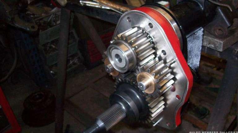
    This is a good shot of the inside of the Tibus Portal, its the prototype so the case and a few components have changed however the principle is still pretty close.


Page 3 of 6 FirstFirst 12345 ... LastLast

Bookmarks

Bookmarks

Posting Permissions

  • You may not post new threads
  • You may not post replies
  • You may not post attachments
  • You may not edit your posts
  •  
Search AULRO.com ONLY!
Search All the Web!