Page 2 of 5 FirstFirst 1234 ... LastLast
Results 11 to 20 of 42

Thread: 101 Handbook

  1. #11
    Join Date
    Jan 1970
    Location
    Canberra
    Posts
    18,616
    Total Downloaded
    0
    Brakes and glass all coming together. Ordered new wheel cylinders and tyres. I will be using cheap MRF tyres to get the truck registered and when they wear out I will put on different rims and radials. These are only rated at 90 kph which is a worry but it seems the original bar treads are the same.

    Anyone know where I can get 101 shock absorber rubbers - I have drawn a blank so far so will be removing a front shocker and hawking it around suspension shops looking for something that will fit.

    Garry
    REMLR 243

    2007 Range Rover Sport TDV6
    1977 FC 101
    1976 Jaguar XJ12C
    1973 Haflinger AP700
    1971 Jaguar V12 E-Type Series 3 Roadster
    1957 Series 1 88"
    1957 Series 1 88" Station Wagon

  2. #12
    Join Date
    Jan 2008
    Location
    Nowra NSW
    Posts
    3,906
    Total Downloaded
    0
    I need shocker rubbers too.
    I think Anthony in Melb has them and the former owner of my machine has some.....the prices are at work?
    The rubber and shockers are similar to early Bedford truck.
    Shock rubbers are a common 101 replaced part.
    My 101 has the transfer cable out of it at the moment.
    This photo shows the layout.
    See the small thumb wheel near the lever bracket.......this had a U shaped end on it for the hand throttle.
    The black knob forward of it is the current hand throttle for the winch.
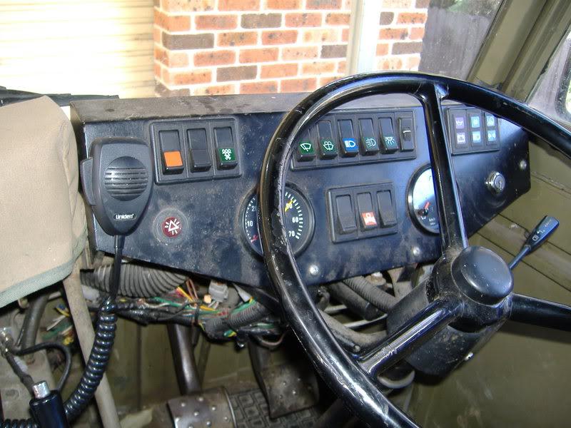
    The radio has replaced the two rapier amp and volt guages.
    The handle is of a axe in the rifle holders.
    A CB radio is screwed on to the heater housing and a clock near by.
    101levers004.jpg - Image - Photobucket - Video and Image Hosting
    Last edited by Lotz-A-Landies; 15th February 2008 at 06:31 PM.

  3. #13
    Join Date
    Jan 2008
    Location
    Nowra NSW
    Posts
    3,906
    Total Downloaded
    0
    Last edited by Lotz-A-Landies; 15th February 2008 at 06:28 PM.

  4. #14
    Join Date
    Jan 2008
    Location
    Nowra NSW
    Posts
    3,906
    Total Downloaded
    0
    Last edited by Lotz-A-Landies; 15th February 2008 at 06:29 PM.

  5. #15
    Join Date
    Jan 2008
    Location
    Nowra NSW
    Posts
    3,906
    Total Downloaded
    0
    My dash board is non standerd as most people cannot handle the 24 volt electrics......this was done by a previous owner and wiring wise has caused much pain.
    101levers002.jpg - Image - Photobucket - Video and Image Hosting


    101Ron - Photobucket - Video and Image Hosting
    Last edited by Lotz-A-Landies; 15th February 2008 at 06:30 PM.

  6. #16
    Join Date
    Jan 2008
    Location
    Nowra NSW
    Posts
    3,906
    Total Downloaded
    0
    This is the extra fuel pump.
    On the chassis rail you can see the LP Gas supply hose.
    The end of the overdrive shift linkage is in view without the cable or transfercase top angle bracket..
    101levers008.jpg - Image - Photobucket - Video and Image Hosting

  7. #17
    Join Date
    Jan 2008
    Location
    Nowra NSW
    Posts
    3,906
    Total Downloaded
    0
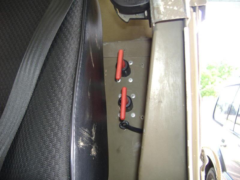
    This is the battery oscillator switches as the vehicle is now 12volt running two 12 volt batterys......just down the side of the left hand seat.
    001-2.jpg - Image - Photobucket - Video and Image Hosting
    Last edited by Lotz-A-Landies; 15th February 2008 at 06:52 PM.

  8. #18
    Join Date
    Jan 2008
    Location
    Nowra NSW
    Posts
    3,906
    Total Downloaded
    0
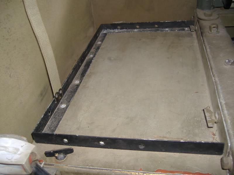
    Alloy angle pop riveted to the top of the battery cover so things can be placed there and not roll off.
    002-2.jpg - Image - Photobucket - Video and Image Hosting
    Last edited by Lotz-A-Landies; 15th February 2008 at 06:52 PM.

  9. #19
    Join Date
    Jan 2008
    Location
    Nowra NSW
    Posts
    3,906
    Total Downloaded
    0
    Overdrive and where the screw driver is a shorten rangie shift handle lever will connect to the overdrive gear change cable.
    101levers007-1.jpg - Image - Photobucket - Video and Image Hosting
    Last edited by Lotz-A-Landies; 15th February 2008 at 06:53 PM.

  10. #20
    Join Date
    Jan 2008
    Location
    Nowra NSW
    Posts
    3,906
    Total Downloaded
    0
    This shows the engine driven compressor were the 24 volt altenator used to be.
    Gas convertor can be seen and the gas supply via century underthrottle valve into the exsiting manifold balance ports.
    A 12 volt altenator is fitted low on the LHS of the motor. not in view.
    003-3.jpg - Image - Photobucket - Video and Image Hosting
    Last edited by Lotz-A-Landies; 15th February 2008 at 06:50 PM.

Page 2 of 5 FirstFirst 1234 ... LastLast

Bookmarks

Bookmarks

Posting Permissions

  • You may not post new threads
  • You may not post replies
  • You may not post attachments
  • You may not edit your posts
  •  
Search AULRO.com ONLY!
Search All the Web!