

 Reply With Quote
As far as i can tell the only difference is with your old separator is it has the 'start assist' function - Im guessing it might have an input from yje starter solenoid??
it should be an easy enough swap.
why did you chose the traxide system?
Steve.

 Major Part of the Heart and Soul of AULRO
Subscriber
Major Part of the Heart and Soul of AULRO
SubscriberI have an (evidently) clapped out Surepower battery separator, which I need to remove.
separator
I will be replacing it with one of Tims Traxide SC-80 units.
http://www.traxide.com.au/trax1sc80_2.html
Now, while Tim has provided instructions as to how to INSTALL the new unit, what I really need to know is what of all the junk that is currently n my battery box is likely to belong to the surepower thing.
Just the isolator itself you reckon ?
There;s a small fusebox/ fuseholder in there though I suspect that might be to run individual fuses for things like ARB compressor, aux fuel pump etc. Maybe.
It's not broken. It's "Carbon Neutral".
gone
1993 Defender 110 ute "Doris"
1994 Range Rover Vogue LSE "The Luxo-Barge"
1994 Defender 130 HCPU "Rolly"
1996 Discovery 1
current
1995 Defender 130 HCPU and Suzuki GSX1400
Master
As far as i can tell the only difference is with your old separator is it has the 'start assist' function - Im guessing it might have an input from yje starter solenoid??
it should be an easy enough swap.
why did you chose the traxide system?
Steve.
Master
I would agree. In your old system, the two big terminals at the top of the battery isolator connect to your main battery and auxiliary battery respectively. These are all that you need. The spade terminals at the side just allow you to pair the batteries up while you are starting, and separates them afterwards. This will consist of a live feed from the ignition, so either follow the wire back to the ignition and disconnect it, or cut it in the battery box and cap it off carefully, for fear of it shorting out in the future.
To fit the traxide unit, do the following.
1. Disconnect the positive terminals from both batteries.
2. Disconnect the main and aux battery leads from the top of the old isolator.
3. Remove old isolator. Don't remove the fuse box as this is more than likely an aftermarket fuse box added to distribute power from the aux battery to devices such as an air compressor, fridge, etc, and can be used again.
4. Solder the red and yellow wires from the traxide isolator to the MAIN battery lead from the top of the old isolator.
5. Solder the blue and grey wires from the traxide isolator to the AUX battery lead from the top of the old isolator.
6. Connect the green wire from the traxide isolator to ground.
7. Double, triple check everything.
8. Reconnect the batteries.
Hope this helps....
Super Moderator
I have a SurePower Isolator that I have been meaning to install for ages.Originally Posted by mike_ie

Are you suggesting that I can ignore all the blade connectors and only use the two battery terminals? (Assuming that the whole unit is grounded with it's mounting bolts of course.)
Diana
You won't find me on: faceplant; Scipe; Infragam; LumpedIn; ShapCnat or Twitting. I'm just not that interesting.
Master
I'm suggesting that you read the installation manual
I'm not being a trying to be smart, but I'm just going by the SurePower brochure, rather than having a full set of installation instructions in front of me. But from what I can see of the wiring diagrams there, the SurePower Isolator has the following terminals:
Two bolt terminals on top:
- To Main Battery
- To Auxiliary Battery
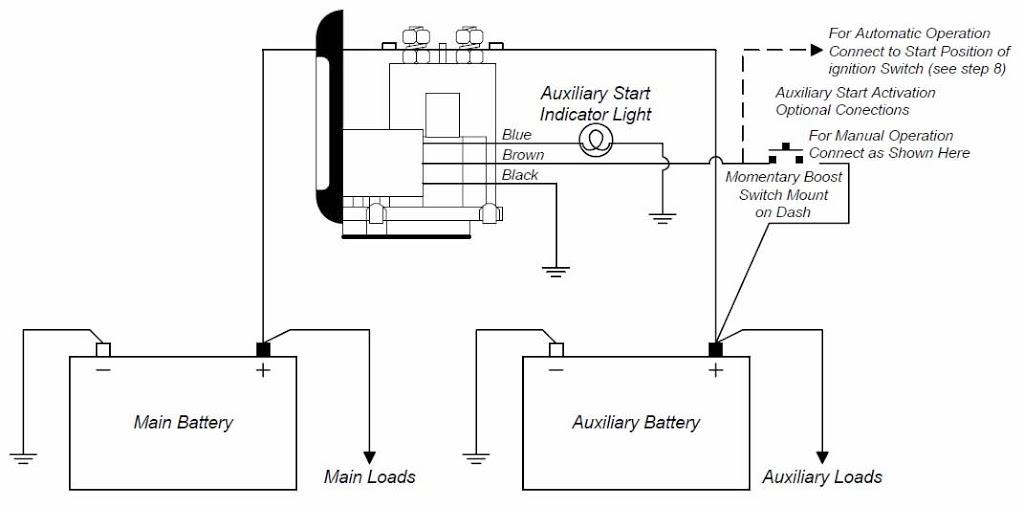
Three spade connectors on the side:
- Start Lamp
- Start Signal
- Ground
My interpretation is that as long as you have the GROUND spade connector connected to the chassis, then the SurePower Isolator should work by simply connecting the MAIN terminal to the main battery, and the AUX terminal to the auxiliary battery. In other words, when you start the car, the main battery charges first, then the auxiliary, and the batteries are isolated from each other at all times.
The Start Assist feature is optional, and uses the START SIGNAL spade terminal. If you apply power to this, both batteries are connected in parallel, until power is removed from the terminal. There are two ways of using this. The first is if you take a wire from the ignition to the terminal. When you turn the key to start the car, it applies power to the terminal and links the batteries, giving you plenty of extra oomph to start the car (12V, but the combined amperage of both batteries). Once you release the key, power is cut and the batteries are isolated. Alternatively you can apply power to the START SIGNAL terminal through a switch in the dash, allowing you to manually bridge the batteries, for example when winching, when you've left the lights on in the car and the main battery has gone flat, etc.
The START LAMP terminal I would assume, can be connected to a bulb to show you when the Start Assist feature is in use.
So to answer your question - you can ignore all the blade connectors EXCEPT GROUND and only use the two battery terminals.
Super Moderator
Yes, in fact you are trying to be smart.
I rather hoped that when you made your first post, that you actually knew what you were saying or better still had done it.
Just to let you know, what you call a "manual" is actually one A4 piece of paper with one side dedicated to what is essentially advertising for the product and the warranty disclaimer. The other side one third is a wiring schematic and the rest a step by step installation procedure.
No where does it mention that you can ignore all of the spade connectors, which is what you suggested when you said "Is there anyone out there who knows what they are talking about?
You won't find me on: faceplant; Scipe; Infragam; LumpedIn; ShapCnat or Twitting. I'm just not that interesting.
Major Part of the Heart and Soul of AULRO
SubscriberLOTZA - ANY CHANCE YOU CAN SCAN AND POST THE STEP BY STEP INSTRUCTIONS / DIAGRAM ?
oops sorry re cais Im not shouting !
It's not broken. It's "Carbon Neutral".
gone
1993 Defender 110 ute "Doris"
1994 Range Rover Vogue LSE "The Luxo-Barge"
1994 Defender 130 HCPU "Rolly"
1996 Discovery 1
current
1995 Defender 130 HCPU and Suzuki GSX1400
Master
Actually I wasn't. I took the trouble of going to the SurePower website, and searching online a bit, and the installation instructions that they issued to you aren't available for download. Their brochure however, does show a diagram of what each terminal is used for - as I listed earlier:
Two bolt terminals on top:
- To Main Battery
- To Auxiliary Battery
Three spade connectors on the side:
- Start Lamp
- Start Signal
- Ground
plus other information that allows one to infer how the device is installed. Not to mention that smart battery isolators are pretty standard when it comes to installation, regardless of manufacturer. As for "being smart", I was merely stating that my instructions were based on this, and you, the purchaser, had the official SurePower instructions out of the box, therefore if you read something that contradicted my post, then follow your instructions, not mine.
If you have a scanner, feel free to scan the schematic side of the "manual" and post it here. I, and I'm sure others, will be happy to try and help.Just to let you know, what you call a "manual" is actually one A4 piece of paper with one side dedicated to what is essentially advertising for the product and the warranty disclaimer. The other side one third is a wiring schematic and the rest a step by step installation procedure.
Again, I don't have the installation schematic, but the brochure states:No where does it mention that you can ignore all of the spade connectors, which is what you suggested when you said....
Start Assist Feature: An optional input from the key switch or a manual switch will program the Battery Seperator to parallel the batteries during starting.
That would (a) highlight the purpose of the START SIGNAL terminal and (b) indicate that it's an optional input.
GROUND is ground, enough said.
START LAMP: My own setup (not SurePower) also has the same terminals, as have two other installations I have helped with. In all three cases the START LAMP (or similarly named) terminal was used to light a globe when the batteries were being paralleled. Again, optional.
I thought I did. Apparently notIs there anyone out there who knows what they are talking about?")
Master
Google is my friend after all, apparently.
Data sheet for a couple of variations of the SurePower Battery Isolators.
http://www.ase-supply.com/v/vspfiles.../1314-1315.pdf
Taken from Page 2:
UNIT CONNECTIONS
The unit has five connections (see Connection Diagram for locations):
- Main Battery connection
This is the high current connection to the main battery. This connection is made directly to the relay. Product labeling refers to this as the MAIN BAT connection. The unit is powered from the main battery connection or the auxiliary battery connection, drawing power from whichever has the higher voltage.- Auxiliary Battery connection
This is the high current connection to the auxiliary battery. Product labeling refers to this as the AUX BAT connection. The unit is powered from the main battery connection or the auxiliary battery connection, drawing power from whichever has the higher voltage.
Note: For the 1315 model, the battery connections can be reversed.- Ground
This is the unit ground connection.- Start Signal input
This is the input for engine start signal override. When power is applied to this input, the relay will close if the Aux. Battery is no less than 0.85 Volts below the Main battery.- Start Lamp output
This is the start lamp drive output. The start lamp is powered when the start signal input has caused the relay to close. This output can source up to 250mA to an incandescent lamp. For LED type indicator, see MAXIMUM RATINGS, START LAMP drive current.
My previous posts were correct, it seems.
Major Part of the Heart and Soul of AULRO
SubscriberI had all sorts of stuff connected to those terminals - not sure whoever had installed it knew all that much about it. I mean the parallel was set up right but there were psoitive cables for variosu accesories also using those spade terminals - confusing the issue.
Anyway I have an SC-80 here and will instal it.
Cheers
It's not broken. It's "Carbon Neutral".
gone
1993 Defender 110 ute "Doris"
1994 Range Rover Vogue LSE "The Luxo-Barge"
1994 Defender 130 HCPU "Rolly"
1996 Discovery 1
current
1995 Defender 130 HCPU and Suzuki GSX1400
 Posting Permissions
| Search AULRO.com ONLY! |
Search All the Web! |
|---|
|
|
|

Bookmarks