Hi Franz, unfortunately there is a lot more info needed to be able to determine whether you have a problem or not.
Forget the readings you get after using a battery charger, they charge batteries in a different way to what happens while your driving.
Now you say your batteries “SETTLED” back to 12.4v.
This does not mean they “DISCHARGED” back to 12.4v and while I was not surprised at the readings you got just an hour and half after your stopped charging the batteries as this was still just surface volts not battery SoC.
Your actually need to leave the batteries in a No Charger/No Load state for at least 24 hours to get any form of true indication of what the real SoC of your batteries.
The other factor for the voltage reading is just how long you drove for before leaving your vehicle for the day and a half?
If you have done a few short drive and then left your vehicle for a day or two, the AGM will normally take a charge quicker that your cranking battery, NOTE this “ONLY” occurs when charging from an alternator, not when using a DC/DC device or battery charger, so if your have done a few short drives, your cranking battery might be down a bit and your AGM is keeping it topped up.
There is an easy way to check if there is a problem. Next time you know you are going to be leaving the vehicle unused for a day or two. Before you turn your motor off, switch the USI-160 In-Cab controller to the IGNITION mode, ( switch the switch towards the LED ) and leave it that way.
In SHARED mode the common battery voltage has to drop to 12.0v before the batteries are separated.
In IGNITION mode once the common voltage drops to 12.6v, the batteries will be separated, so with your USI-160 set to IGNITION mode. the batteries will separate at a much high voltage and you can then see if either ( or both ) battery settles to a lower voltage or just keeps discharging.
Now a note, if your cranking battery is a Calcium/Calcium battery then is it not uncommon for them to settle back as low as 12.2 but they will still be in an excellent condition.
As posted earlier, because of the way my isolators work, they tend to keep cranking batteries in a higher state of charge than normal, and this is why you need to bypass the SHARED mod to test your batteries.
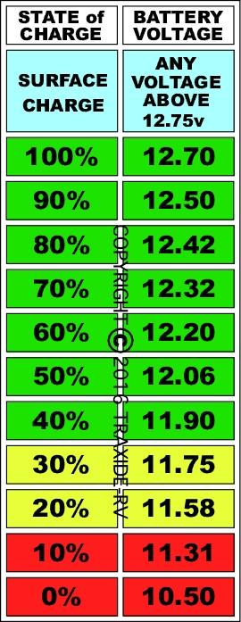
Use the chart below to determine the rough SoC of your batteries.


 Reply With Quote
Originally Posted by garrycol


Bookmarks