Results 1 to 5 of 5

Thread: Traxide Dual Headlight Relay into D2a Installation Guide

  1. #1
    Join Date
    Feb 2011
    Location
    Hobart, Tasmania, Australia
    Posts
    3,828
    Total Downloaded
    0

    Arrow Traxide Dual Headlight Relay into D2a Installation Guide

    Today I installed the dual headlamp relay purchased from Tim at Traxide ( Relay_Info ) into my 2003 Land Rover Discovery HSE TD5 (D2a with the updated/refresh headlights).

    My purpose for this installation was to reduce the voltage drop caused by the headlight switch and MOSFETs in the BCU, and also reduce the load/burden on the headlight switch, as this is believed to be the common cause of the headlight switches failure. For more discussion on this see this thread - http://www.aulro.com/afvb/discovery-...ht-wiring.html
    My intention was not to completely rewire the headlights, as that is too much of a pain since it's internal in the D2a headlamps, and I'm not convinced it was necessary. For a brief discussion on this, see Pauls post in #7 in http://www.aulro.com/afvb/discovery-...eadlights.html


    So here is a basic guide on what I did:

    Preliminary step:
    I had a bunch of connections already to the battery and earth point. It was starting to get a bit messy and cluttered, so the first thing I did was neaten all this up so that I was starting from a nice clean point. The method I chose to do this was to install a Blue Seas 6 Blade Fuse Block with Negative Bus ( https://www.whitworths.com.au/main_i...587&search123= ) underneath my dash.


    This allowed me to have a single main positive wire (8AWG wire rated to 80amp with a Fusion fuse near the battery - left over wiring and fuse from an old car audio installation) running into my cabin and a single earth point. All other connections go to the fuse gang:


    Before you begin:
    Get familiar with the wiring setup of the relay:


    Relay_Info

    Headlight Kit info


    Step 1:
    Select location to install the dual headlight relay. I selected underneath my dash, as I like to have all my fuses and relays in a single location, and also due to the vehicle spending a large amount of time on beaches I wanted to reduce issues caused by corrosion.


    I used double sided tape to hold it in place:


    Step 2:
    Run a power line from the battery to the relay (connect to the B connection on the relay). In my case my power line comes from my fuse gang. The wire should be fused as close to the battery as possible and should be rated to handle the headlights amps - minimum of 20amps, but thicker is better as this will help to reduce voltage drop over the length of the wire (I used 12AWG).

    Step 3:
    Run a earth to the relay (connect to the S connection on the relay). Doesn't have to go to the battery, find a nearby point. This is the earth for the relays, not for the headlights themselves, so a single 5amp wire should be sufficient.


    If you also installed your relay under the dash and are looking for a place to earth it, look up high on the right side of the steering column there is a threaded hole. I use this as my earth point and I mount my relays on it:


    Step 4:
    The relay needs trigger wires to tell it when to activate. You'll need a trigger for low beam and one for high beam. Now initially I was going to run two wires back from the headlights original power wires, but then I realised the headlight switch is just above, so I used these. Here is the information from Rave:


    So you need to tap into the Blue/Red and Blue/White wires from the headlight switch wiring loom. I did this using some Narva Ezy Taps (Fig. 7 Joiners/Wire Taps - Products - Narva ):


    I then put my trigger wires into the factory wiring looms split tube. This helps to protect them and keeps them neat and tidy and factory looking:


    Connect these trigger wires to the relay (connection S1 and S2 - doesn't matter which is which, so long as you match this to the output wires to the correct low or high beam - I used S1 as low beam and S2 as high beam):


    Step 5:
    Now this is where I had to get clever. The plug and play kits available from Traxide are for Defenders and earlier Discoveries which use H4 headlight globes. For those that do not know, H4 is a dual filament globe and switches filaments for low and high beam.
    However, on the D2a, using it's projector headlights, when high beam is activated, both the low and high beam bulbs are illuminated.
    So the issue here is that I needed to come up with a way to trigger the low beam circuit to activate with the high beam circuit (but it could only be one way as we don't want the high beam circuit running when only the low beam is activated).
    To achieve this I found a diode lying around it is a 1N4044 (I think), it looks pretty small, and I don't know what it's actually rated (the internet tells me 400v 1A) so I was concerned that it might be too small (it's a minor item, I can upgrade it later on), but since I didn't have anything else I gave it a go. I made a jumper lead to go from the two trigger connections on the dual relay. The diode is a one direction device that only allows the current to flow one way.


    Now connect this from S1 to S2 on the dual relay. The diode should have a silver band to show it's current flow direction. If it's not working properly then you likely have it the wrong way and just need to turn it around.


    Step 6:
    Remove the grill, headlamp protectors (if fitted) and headlamps as if you are changing the light globes (check out your Owners Manual if you need more help on this one).

    Step 7:
    Disconnect the electrical connection from the headlamps.

    Step 8:
    Work out which wire is the positive for low and high beam. It should be the middle two on the bottom row of the electrical connection (wires 7 and 8 I think), when you hold it with the small wires on top, the left one is the high beam and right one is the low beam (I can't remember colours, one is Blue/Orange and one is Blue/Grey - I used a multimeter to confirm).

    Step 9:
    Cut these wires leaving enough wire on either side to add connections.

    Step 10:
    I fitted Narva flat terminal connections on either end. Ensure you put the insulated female on the wire side furthest away from headlight as this wire is live when the headlamp switch is activated and therefore will blow fuses if earthed.
    Ensure you do this to both sides.
    The reason for the connections and not soldering, is because if the dual relay ever fails, I can quickly reconnect the factory headlight wiring and continue on - it would take as long time was as it would to change a light globe. It is also handy for problem solving and future issues with the headlights (if any arise).


    Step 11:
    Run two wires from the passenger side headlight connection to near the drivers side. 5 amp wiring would probably only just be sufficient, but I used 15amp wiring. Colour code these for identification of high and low beam.
    Connect these on the passenger side into the headlight wiring loom to the headlight side. These will be the power wires for the passenger side headlamp.

    IMG_1584.jpg picture by twr7cx - Photobucket

    Step 12:
    Run two wires from the dual relay to the drivers side headlight. Connect these into the headlight wiring loom to the headlight side. These will be the power wires for the drivers side headlamp.
    On the relay side connect these to L1 and L2 - now ensure these match the trigger wires that you connected in Step 4. So I connected my low beam trigger to S1, so I connect my low beam power wire to L1. I connected my high beam trigger wire to S2, so my high beam power wire comes from L2.
    These wires need to be a minimum of 10 amps (as they are carrying the power from both drivers and passenger side headlights), but again I used 15 amp.
    Ensure you match your colour coding from Step 11.

    Step 13:
    Tap the wires from Step 11 into the wires from Step 12. I used Narva Ezy Taps.

    Step 14:
    Test your setup, if it works, refurb the vehicle in reverse.


    (840watts in the above setup - 6x 100w lights, 4x55w and 4x5w)

  2. #2
    Join Date
    Feb 2011
    Location
    Brunswick, Victoria
    Posts
    3,778
    Total Downloaded
    0
    Glad it's your D2, not mine.

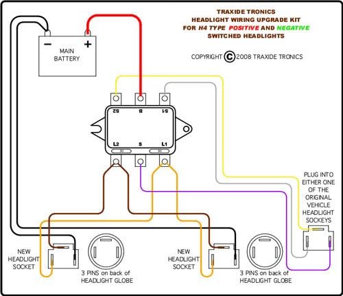
    Done properly these upgrades shouldn't need any wiring to the cabin. The main advantage of the relay comes from having a short wire run from battery to globe. You've lost that advantage by running the power wiring back into the cabin.

  3. #3
    Join Date
    Feb 2011
    Location
    Hobart, Tasmania, Australia
    Posts
    3,828
    Total Downloaded
    0
    Quote Originally Posted by OffTrack View Post
    I'm baffled as to why you decided to put the relays under the dash???
    Because the engine bay of my vehicle has salt water flicked around it on almost a daily basis during summer. It causes corrosion issues etc. Having it under the dash prevents some of these components from being exposed.
    I also have a lack of room in my engine bay. After fitting a second battery to the passenger side back corner, diff/transfer box/transmission breather filters to the drivers side back corner, and secondary transmission cooler behind the front grill, I'm running out of real estate.

  4. #4
    Join Date
    Dec 2012
    Location
    Mountains/Central West NSW
    Posts
    111
    Total Downloaded
    0
    Not aways appreciated is the concept that voltage drop occurs over the WHOLE circuit. Thus also upgrading the size of the earth (or -ve) wires to the headlamps should have a further beneficial effect. The diagrams on the Traxide website seem to suggest this additional wiring.

  5. #5
    schuy1 Guest
    A wee bit complicated but a good job if it achieved your aims! With your saltwater issues I think I would have used waterproof connecters to the headlights . For ever1 doing wiring remember its a circuit, So 10 amps in , 10 amps back to earth, so the wiring reflects that ,I have always erred on the side of larger earths to allow for resistance buildup,
    BTW I HATE saltwater!

Bookmarks

Bookmarks

Posting Permissions

  • You may not post new threads
  • You may not post replies
  • You may not post attachments
  • You may not edit your posts
  •  
Search AULRO.com ONLY!
Search All the Web!