

 Reply With Quote
So am I correct in now saying that
1: Battery
2: Illumination
3: not used
4: Relay
5: Earth
Is this correct when using a Freelander Cruise switch?

 Fossicker
It would been perhaps more helpful if you'd actually mentioned that the defender spotlight switch was an example of a different type of switch. I read it as you were showing an example of the switches you had previously been talking about. Here I was trying to figure out why on earth you're saying pin 5 is earth when it clearly wasn't.Originally Posted by PaulMc0308

Anyway. Now I'm all caught up, and if I have to wire another driving light switch at some stage, I'll certainly be looking for a cruise switch, bit less stuffing around to wire up than what I used (which I now remember was a rear fog switch with the latching mechanism from a rear wiper swapped in, effectively giving me the same as your defender spotlight switch).
Fossicker
So am I correct in now saying that
1: Battery
2: Illumination
3: not used
4: Relay
5: Earth
Is this correct when using a Freelander Cruise switch?
Fossicker
You're right, re-reading it, it's not as clear as I intended
I've edited my post to, hopefully, rectify that.
Paul.
1989 Arles Blue 2.5TD 110 Hardtop
1999 Epsom Green Discovery II 4.0 V8i 'XS'
.
Fossicker
Correct
Paul.
1989 Arles Blue 2.5TD 110 Hardtop
1999 Epsom Green Discovery II 4.0 V8i 'XS'
.
Fossicker
All sorted and working!
thanks for the help everyone!
(Ill add that half my problem was i had power going into pin 4 and relay into pin 1- hence why the LED always had power)
Master
Sorry to cause all of the confusion but correct me if I am wrong .
Does LR not use a common switch and terminals when getting feed back for indication,I did note that all the other switches on the puma dash were using pin 5 as earth
Thanks again for the information Paul
Fossicker
If only it were that easy
On most of the Defender/D2/Freelander switches -
Live-switching switches use pin 5 for their earth
Earth-switching switches use pin 4 for their earth
There are also some switches on the D2, that use pin 2 for their earth -
Rear wash/wipe switch, HDC switch, fuel flap release switch
All the info is in the RAVE Electrical Wiring Diagrams and Electrical Library.
Paul.
1989 Arles Blue 2.5TD 110 Hardtop
1999 Epsom Green Discovery II 4.0 V8i 'XS'
.
ForumSage
SubscriberI have just finished having a play with my switch which is a D2 cruise switch and yes the above is correct for it, however if you just supply battery power to pin one your aux lights will operate on low and high beam, which is not legal
An alternative is to supply pin one with a positive feed from either the light switch high beam or run a feed from a wire spliced into the high beam near the headlight.
If done this way though the orange tell tail light in the switch will only illuminate when the lights are on. I want this light illuminated when the switch is depressed regardless of the aux lights status.
I will achieve this by supplying a 12 volt feed to pin one from the fuse box. Pin 4 will then go to a relay pin 87. pin 30 will then go to aux lights relay/s.
A feed from cars high beam will go to pin 86 and pin 85 to earth.
Could do a wiring diagram if you want

Dave.
I was asked " Is it ignorance or apathy?" I replied "I don't know and I don't care."
1983 RR gone (wish I kept it)
1996 TDI ES.
2003 TD5 HSE
1987 Isuzu County
Master
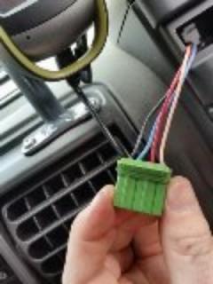
I've just tackled this myself but I used a rear wiper switch.
Since the light stalk is on the left of the steering wheel, I decided to use one of the three blank switch points. Upon closer inspection, i found that the second from the top one (blanked off in my disco) had a plug there that was wired into the loom. This would be for front fog lamps but I don't have any.
The setup of the wiring is as per Paul's post and is dead simple to do.
One unused fog lamp plug, rewired.
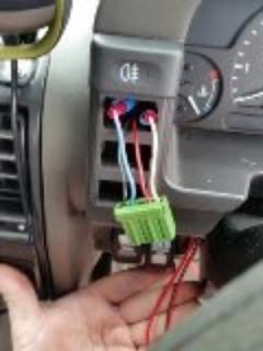
Now with the wires tapped to get the high beam signal and send the signal to the relay. Wires have been run to under the dash and can be seen at the bottom of the pic.
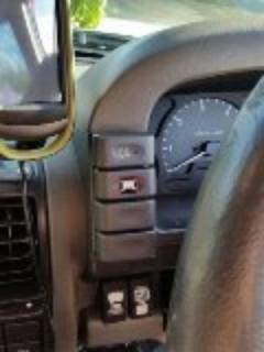
Once the switch has been rewired, on with my custom switch face. This was done by lightly sanding off the paint to present an opaque panel. A light bar sticker from a Narva kit and some permanent marker to clean up the look of things and it looks pretty neat.
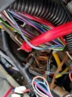
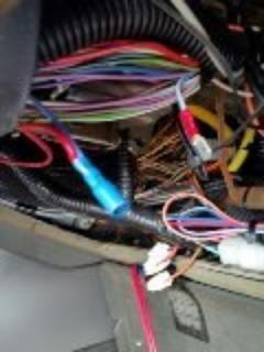
Next job was to find the high beam wire from the steering wheel. I opened up the conduit containing all the steering wheel wires and set about the task of testing and finding the high beam wire. This was eventually done and it is a white wire with blue trace.
Taking the appropriate wire going to the switch, this high beam wire was tapped into.
Just about finished under the dash now. All that remains is to run the signal wire to the relay which I located to the rear of the under bonnet fuse box.
Once the wire is run, clean up under the dash and move to the engine bay.
The engine bay work is pretty straightforward. Find a 12v +ve to run to the relay, an earth for the relay and one for the light bar, hook up the signal wire from the cabin switch to the relay and run the positive for the light bar to the signal out from the relay. Et, voila!
You now have a working lightbar that can only come on with high beam and has an isolation switch. This makes it a roadworthy setup and by using some of the switch blanks left by Land Rover, it looks pretty neat as well.
 Posting Permissions
| Search AULRO.com ONLY! |
Search All the Web! |
|---|
|
|
|


Bookmarks