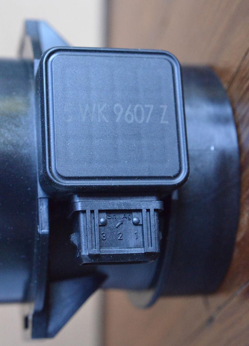
Page 3 of 4 FirstFirst 1234 LastLast
Results 21 to 30 of 37

Thread: First run of new evo-logged Air flow circuit HIGH

  1. #21
    Join Date
    Jan 1970
    Location
    Avoca Beach
    Posts
    14,152
    Total Downloaded
    0
    OK will do when it stops raining sometime this week.

    "Rainfall is never going to reach levels previously enjoyed. Sydney reservoirs will probably never fill again" Paraphrase.
    Regards Philip A

  2. #22
    Join Date
    Feb 2011
    Location
    Brunswick, Victoria
    Posts
    3,778
    Total Downloaded
    0
    Quote Originally Posted by mturri View Post

    Have a few more on the shelf that haven't had the time to test, on the project list though.

    Would be interesting to see what PhillipA's seemingly hypertrofic MAF resistivity readings are...

    Cheers
    Matt
    Hi Matt,

    We've seen a few brand new VDO Siemens that read 21 Mohm out of the box and work perfectly.

    My MAF is reading 15.4M Ohm on pins 1-3 and 2-3 but will still register 645 kg/h at full load.

    I'm inclined to think that your classification "dodgy" is perhaps kicking in too early and down to 15M Ohm at least the MAF should still be perfectly functional. Describing a 19.34 MOhm reading as dodgy seems a little odd when a new VDO unit reads 21MOhm. This figure was seen by myself , and by another member who checked on 3 meters including a calibrated meter at his workplace.

    I'd also be interested in seeing resistance readings from Philips superMAF. Maybe we can organise something?

    cheers
    Paul

  3. #23
    Join Date
    Mar 2010
    Location
    Patagonia
    Posts
    124
    Total Downloaded
    0
    Quote Originally Posted by OffTrack View Post
    I'm inclined to think that your classification "dodgy" is perhaps kicking in too early and down to 15M Ohm at least the MAF should still be perfectly functional. Describing a 19.34 MOhm reading as dodgy seems a little odd when a new VDO unit reads 21MOhm. This figure was seen by myself , and by another member who checked on 3 meters including a calibrated meter at his workplace.
    Point taken. Have removed the subjective bits. The point being illustrated is the apparent correlation between the decrease in 1-3 & 2-3 resistivity values and 'MAF wear'.

    Cheers
    Matt

  4. #24
    Join Date
    Feb 2011
    Location
    Brunswick, Victoria
    Posts
    3,778
    Total Downloaded
    0
    Quote Originally Posted by mturri View Post
    Point taken. Have removed the subjective bits. The point being illustrated is the apparent correlation between the decrease in 1-3 & 2-3 resistivity values and 'MAF wear'.

    Cheers
    Matt
    Hi Matt,

    The MAF wear is interesting, and would be good to get a better idea of the acceptable limits.

    It's pretty astounding the difference cleaning makes:

    MAF before cleaning:

    1-2 16.75 kΩ
    1-3 2.405MΩ
    2-3 14.35MΩ

    MAF after cleaning

    1-2 16.73kΩ
    1-3 15.41MΩ
    2-3 15.50MΩ

    2-3 seems far less sensitive to contamination of the elements than the other two, and 1-2 is apparently unaffected.
    The discrepancy between 1-3 and 2-3 seems a good way of identifying a dirty MAF.

    cheers
    Paul

  5. #25
    Join Date
    Jan 1970
    Location
    Avoca Beach
    Posts
    14,152
    Total Downloaded
    0
    before I go further , which do you consider 1?
    Towards Front of car or rear.
    Regards Philip A

  6. #26
    Join Date
    Mar 2010
    Location
    Patagonia
    Posts
    124
    Total Downloaded
    0
    Quote Originally Posted by PhilipA View Post
    before I go further , which do you consider 1?
    Towards Front of car or rear.
    Should be rear...


  7. #27
    Join Date
    Jan 1970
    Location
    Perth WA 6149
    Posts
    1,308
    Total Downloaded
    0
    I worked it out by multi meter and looking for 16.7Kohm, logically pin 2 is centre so it was a 50/50 chance: from there p

    My new VDO MAF tested in the mid 20 Mohms across pins 1-3 and 2-3.

    Cheers

    Steve

  8. #28
    Join Date
    Feb 2011
    Location
    Brunswick, Victoria
    Posts
    3,778
    Total Downloaded
    0
    Just noticed the symbols between the numbers.

    au is Silver element
    sn is Tin element

    I'm wondering how much influence ambient temps have on the resistance readings? The resistance should increase as the temperature rises, so you'd expect to see some variance in resistance with a 20-30°C ambient temp change.

    cheers
    Paul

  9. #29
    Join Date
    Jan 2009
    Location
    Springwood
    Posts
    161
    Total Downloaded
    0
    Thought I might post a link up a very basic tutorial on how a Hot film MAF works (altough this converts the analogue signal to digital.
    http://training.avme.net/admin/Upload/SSP/4864_358%20Hot%20film%20Air%20mass%20meter%20HFM%2 06.pdf

    Resistance testing has so limited use. It will never show a good MAF sensor and will not find alot of bad ones and unlikly a contaminated one. Just to many variables. It's like testing your hot water thermostat with a multimeter at the power board outside your house. Too much inbetween.
    Ambient temp is one variable. Another is your multimeter, the way it measures resistance, the direction of current flow working on the internal cicuitry.
    Contamination causes problems as it basically wraps the thermistor and element in a blanket therefore reducing the cooling effect of airflow. The microcontroller sees this as reduced air flow and reacts accordingly. This is why a resistance test is unlikly to show a contaminated sensor.

    Live data is will give some info on what the state of your MAF sensor is. A scope also helps - on a diesel there is less feed back but it's still good for a reaction test.

    Looking at the live data. The one thing that looks strange to me, not nessisarily the problem, but something I would keep in the back of my mind. Is this vehicle appears to gain altitude faster than a fighter jet around the point the fault occurs. The baro figures are all over the place.
    As I said, just something I would keep in the back of my mind.

    HTH

  10. #30
    Join Date
    Feb 2011
    Location
    Brunswick, Victoria
    Posts
    3,778
    Total Downloaded
    0
    The AAP on the intake side of the air filter so most of the variability is related to the amount of air being drawn into the turbo. As boost increases the depression cause by the airfilter also increases. When the engine limits you tend to see rapid changes of atmospheric pressure due to the turbo spooling down.

    I couldn't see anything in PhilipA's recordings that were suggestive of am AAP sensor problem.

    The boost figure are all over the place because the MAP is overreading and the ECU is rolling the airflow figure to 0 resulting in fuelling being cut. I think it's fairly safe to say it a symptom rather than the cause.

    cheers
    Paul

Page 3 of 4 FirstFirst 1234 LastLast

Bookmarks

Bookmarks

Posting Permissions

  • You may not post new threads
  • You may not post replies
  • You may not post attachments
  • You may not edit your posts
  •  
Search AULRO.com ONLY!
Search All the Web!