Page 2 of 3 FirstFirst 123 LastLast
Results 11 to 20 of 21

Thread: Clutch Modification

  1. #11
    Join Date
    Jan 1970
    Location
    Irymple, Victoria, Australia
    Posts
    2,902
    Total Downloaded
    0
    Quote Originally Posted by bobslandies View Post
    Hi Lionel,

    At first Holden clutches were the most likely used - particularly with the Johnson kit from Geelong. Their kits were very well made and marketed throughout Australia. They are cast and machined steel.

    The fabricated and welded steel adaptors made by Roy Sim in Sydney and others used the Vauxhall and a couple of other pressure plates and Land Rover clutch plates. later Roy designed a Holden flywheel that was slightly larger in diameter and would take a standard Land Rover clutch complete.

    Cast and machined aluminium adaptors were/are made but were often not made to the tolerances required, similarly machined steel flywheels to use Land Rover clutches glazed up badly and were a failure.

    I think all these kits used the Holden Starter Motor.


    There were also some early adaptions using a re-drilled original alloy Land Rover 4 cyl engine to flywheel adaptor that did use the Land Rover Starter Motor. I have seen grey Holden, Vanguard and Falcon motors fitted up this way. Don't know how well they were put together and if they lasted.

    Glad you are happy with your vehicle that has obviously stood the test of time. Best thing we could do to a Land Rover in the 'seventies. A 186 done properly with either an increased sump capacity or an engine oil cooler, seal up the three holes in the bottom of the distributor, slight adjustments to the carburettor, change the differential ratios to 4.3:1 (from Rover 90s) and get over 17mpg from a 109" !!!

    Bob
    Howdy Bob,
    Interesting article!
    I have an 88 with a crude conversion (Holden 173ci) that has a redrilled Landy flywheel and utilised the Land Rover starter motor. It looks extremely rough but works well and offers good pulling power off the mark with the heavier flywheel (approx 4kg) Can you tell me more about the distributor modification and other adjustments to perfect a Holden transplant?

    Cheers Mick.
    1974 S3 88 Holden 186.
    1971 S2A 88
    1971 S2A 109 6 cyl. tray back.
    1964 S2A 88 "Starfire Four" engine!
    1972 S3 88 x 2
    1959 S2 88 ARN 111-014
    1959 S2 88 ARN 111-556
    1988 Perentie 110 FFR ARN 48-728 steering now KLR PAS!
    REMLR 88
    1969 BSA Bantam B175

  2. #12
    Join Date
    Dec 2007
    Location
    Sydney, you know. The olympic one.
    Posts
    4,853
    Total Downloaded
    0
    All the conversions I've seen have used a custom flywheel to use the rover clutch & pressure plate. There were types for both the earlier (borg & beck) and later (diaphragm) types and used the holden starter. Later, as they became available used gear reduction starters.

  3. #13
    Join Date
    Jul 2006
    Location
    Seaforth NSW
    Posts
    933
    Total Downloaded
    0

    Getting the best from a Holden Red Motor conversion

    Quote Originally Posted by mick88 View Post
    Howdy Bob,
    Interesting article!
    I have an 88 with a crude conversion (Holden 173ci) that has a redrilled Landy flywheel and utilised the Land Rover starter motor. It looks extremely rough but works well and offers good pulling power off the mark with the heavier flywheel (approx 4kg) Can you tell me more about the distributor modification and other adjustments to perfect a Holden transplant?

    Cheers Mick.
    Hi Mick,

    There are three holes about 1/4" in the bottom of the "bowl" of the distributor. We would put three pull through type sealed grommets into these holes to stop water splash from below the engine getting into the distributor. To do this you do have to disassemble the distributor or you can just plug the holes with silastic or similar. Some people closed off two holes and fitted a tube from the third up to the air cleaner to purge the distributor of condensate also. Others made shields to stop the splash too.

    There were also two types of carburettor base - manual and auto versions. The difference was in the distributor vacuum advance tube take-off point for manual or auto - above or below the throttle body butterfly. By the HR models most Holdens were fitted with Automatic Transmissions so it was likely if using a second-hand or reconditioned motor that you ended up with an "Automatic" version. When fitted in a Land Rover you needed a "Manual" version carburettor or the engine would hesitate or snatch when you started off. Even on a 202 the carby rebuilders used to recommend a 186 carburettor as they worked better. They would set the float level a bit lower than Holden specifications to compensate for the angle that the engine sat in the Land Rover, otherwise they could flood on steep climbs.

    Different capacity motors 149 through 202 have a range of increasing bore sizes from IIRC 1 3/32" to 1 7/32" so you need to be sure you have the correct match for the engine capacity as well as a "Manual" version.

    The water temperature regulated inlet manifolds should be set up properly with water flow as this keeps the carburettor at the best operating temperature.

    We got rid of the oil bath air cleaners and replaced them with the Holden "taxi" or "outback" heavy duty air cleaners incorporating both a paper element and a oil wettened foam surround. This freed up the area where the oil bath cleaner had been behind the battery for a second battery.

    Because different Holden sumps had the bulge for oil pickup in different places relative to the Holden front suspension, chassis, etc the best sump for oil pickup had the bulge in the centre - the HK was the one I had in mine - you had to use the matching pickup tube. This would alleviate oil starvation either up or down hill.

    As I said earlier the Holden engine oil capacity was a bit small for a heavier vehicle expected to run at higher revs than in a car. Either increasing the capacity of the sump or better still adding a wafer adaptor between the oil pump and the oil filter with hoses to a decent sized oil cooler mounted in front of the radiator was the solution there. In cooler parts of Australia a thermostatically controlled bypass in the line allowed the oil to heat up and then kept the oil at the correct operating temperature.

    Different camshafts were evaluated and the 186A (HR) and 186P (HK) engines had the best torque characteristics with max torque at 1600 rpm.
    All the larger capacity red motors were 9.2:1 compression and the only real differences were the other versions had their maximum torque at higher (up to 2200) rpm. If you wanted more power on the road a dual barrel Stromberg WW carburettor from the 186S vehicles was the way there. 173s have their maximum torque at 2000 rpm.

    If I think of anything else I will add it in another post.

    Bob

  4. #14
    Join Date
    Mar 2010
    Location
    Queensland
    Posts
    4,125
    Total Downloaded
    12.97 MB
    Quote Originally Posted by bobslandies View Post
    Hi Mick,

    There are three holes about 1/4" in the bottom of the "bowl" of the distributor. We would put three pull through type sealed grommets into these holes to stop water splash from below the engine getting into the distributor. To do this you do have to disassemble the distributor or you can just plug the holes with silastic or similar. Some people closed off two holes and fitted a tube from the third up to the air cleaner to purge the distributor of condensate also. Others made shields to stop the splash too.

    There were also two types of carburettor base - manual and auto versions. The difference was in the distributor vacuum advance tube take-off point for manual or auto - above or below the throttle body butterfly. By the HR models most Holdens were fitted with Automatic Transmissions so it was likely if using a second-hand or reconditioned motor that you ended up with an "Automatic" version. When fitted in a Land Rover you needed a "Manual" version carburettor or the engine would hesitate or snatch when you started off. Even on a 202 the carby rebuilders used to recommend a 186 carburettor as they worked better. They would set the float level a bit lower than Holden specifications to compensate for the angle that the engine sat in the Land Rover, otherwise they could flood on steep climbs.

    Different capacity motors 149 through 202 have a range of increasing bore sizes from IIRC 1 3/32" to 1 7/32" so you need to be sure you have the correct match for the engine capacity as well as a "Manual" version.

    The water temperature regulated inlet manifolds should be set up properly with water flow as this keeps the carburettor at the best operating temperature.

    We got rid of the oil bath air cleaners and replaced them with the Holden "taxi" or "outback" heavy duty air cleaners incorporating both a paper element and a oil wettened foam surround. This freed up the area where the oil bath cleaner had been behind the battery for a second battery.

    Because different Holden sumps had the bulge for oil pickup in different places relative to the Holden front suspension, chassis, etc the best sump for oil pickup had the bulge in the centre - the HK was the one I had in mine - you had to use the matching pickup tube. This would alleviate oil starvation either up or down hill.

    As I said earlier the Holden engine oil capacity was a bit small for a heavier vehicle expected to run at higher revs than in a car. Either increasing the capacity of the sump or better still adding a wafer adaptor between the oil pump and the oil filter with hoses to a decent sized oil cooler mounted in front of the radiator was the solution there. In cooler parts of Australia a thermostatically controlled bypass in the line allowed the oil to heat up and then kept the oil at the correct operating temperature.

    Different camshafts were evaluated and the 186A (HR) and 186P (HK) engines had the best torque characteristics with max torque at 1600 rpm.
    All the larger capacity red motors were 9.2:1 compression and the only real differences were the other versions had their maximum torque at higher (up to 2200) rpm. If you wanted more power on the road a dual barrel Stromberg WW carburettor from the 186S vehicles was the way there. 173s have their maximum torque at 2000 rpm.

    If I think of anything else I will add it in another post.

    Bob

    G'day Bob & Mick,

    Firstly thank you Bob for posting up such comprehensive information. Mick a quick apology for side tracking your thread. I thought since there was a current clutch thread going why start another one and clutter the system up.

    Bob you mentioned about putting an oil cooler in, would this just be for the engine or would it also be advisable to get a transmission cooler as well? Was it just the engine oil temperature which the major concern and the original transmission remained happy just how it was? I intend doing some towing and my first big trip will most likely be during the hotter part of the year.

    What would you consider dimension wise - a "decent sized" oil cooler?

    Do they still make the taxi - or outback version of the air cleaner? It has been a long time since there were straight six Holden taxis.

    Thank you again Bob, and Mick it looks like I have diverted your thread again - sorry mate.

    Kind Regards
    Lionel

  5. #15
    Chris72 Guest
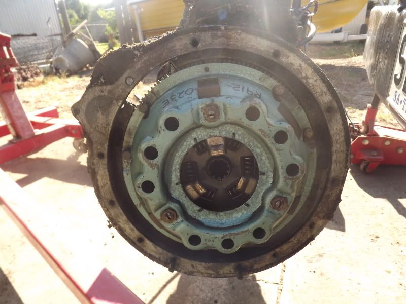
    I might be able to help out with some pic's here is the conversion that was on my series 1 when I bought it, it uses the holden fly wheel thats been redrilled to suit, I think it's the landy pressure plate and clutch, will get other pic of holden pressure plate tomorrow.

    [IMG][/IMG]

  6. #16
    Join Date
    Jan 1970
    Location
    Irymple, Victoria, Australia
    Posts
    2,902
    Total Downloaded
    0
    Thanks Chris,
    a very helpfull pic.
    It looks to have the bolts holding the pressure plate on tapped into the ring gear? Is that how it is? If so it's a wonder the ring gear hasn't slipped under load or are they overlapping into the flywheel as well?

    Cheers, Mick.
    Last edited by mick88; 20th July 2013 at 02:08 PM. Reason: typo
    1974 S3 88 Holden 186.
    1971 S2A 88
    1971 S2A 109 6 cyl. tray back.
    1964 S2A 88 "Starfire Four" engine!
    1972 S3 88 x 2
    1959 S2 88 ARN 111-014
    1959 S2 88 ARN 111-556
    1988 Perentie 110 FFR ARN 48-728 steering now KLR PAS!
    REMLR 88
    1969 BSA Bantam B175

  7. #17
    Join Date
    Jan 1970
    Location
    Irymple, Victoria, Australia
    Posts
    2,902
    Total Downloaded
    0
    There were also two types of carburettor base - manual and auto versions. The difference was in the distributor vacuum advance tube take-off point for manual or auto - above or below the throttle body butterfly. By the HR models most Holdens were fitted with Automatic Transmissions so it was likely if using a second-hand or reconditioned motor that you ended up with an "Automatic" version. When fitted in a Land Rover you needed a "Manual" version carburettor or the engine would hesitate or snatch when you started off. Even on a 202 the carby rebuilders used to recommend a 186 carburettor as they worked better. They would set the float level a bit lower than Holden specifications to compensate for the angle that the engine sat in the Land Rover, otherwise they could flood on steep climbs.

    Bob,
    Firstly thankyou for your very helpfull post.
    I have a "T" piece on the manifold at the back of the motor where the vacuum line for the brake booster is located and that is where I also pick up vacuum for the distributor advance. It seems to work well enough, but do you think I should relocate it? I am running the later model Bosch HEI distributor.

    Cheers, Mick.
    1974 S3 88 Holden 186.
    1971 S2A 88
    1971 S2A 109 6 cyl. tray back.
    1964 S2A 88 "Starfire Four" engine!
    1972 S3 88 x 2
    1959 S2 88 ARN 111-014
    1959 S2 88 ARN 111-556
    1988 Perentie 110 FFR ARN 48-728 steering now KLR PAS!
    REMLR 88
    1969 BSA Bantam B175

  8. #18
    Chris72 Guest
    Quote Originally Posted by mick88 View Post
    Thanks Chris,
    a very helpfull pic.
    It looks to have the bolts holding the pressure plate on tapped into the ring gear? Is that how it is? If so it's a wonder the ring gear hasn't slipped under load or are they overlapping into the flywheel as well?

    Cheers, Mick.
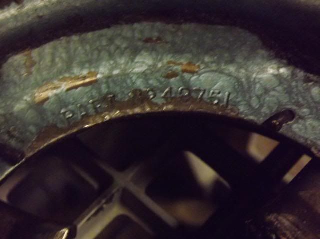
    I Haven't taken the other pic's yet been a hectic day, the fly wheel and pressure plate in the photo is now off the motor so I can take pic's of the individual parts along with part numbers if this will help.

  9. #19
    Chris72 Guest
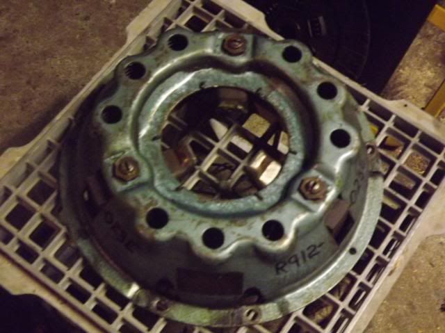
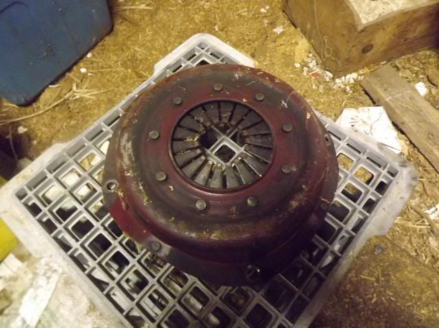
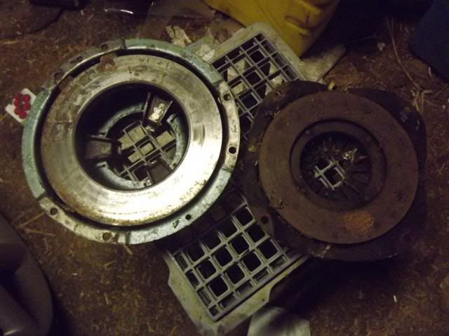
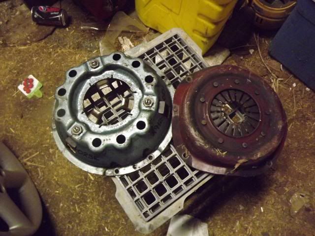
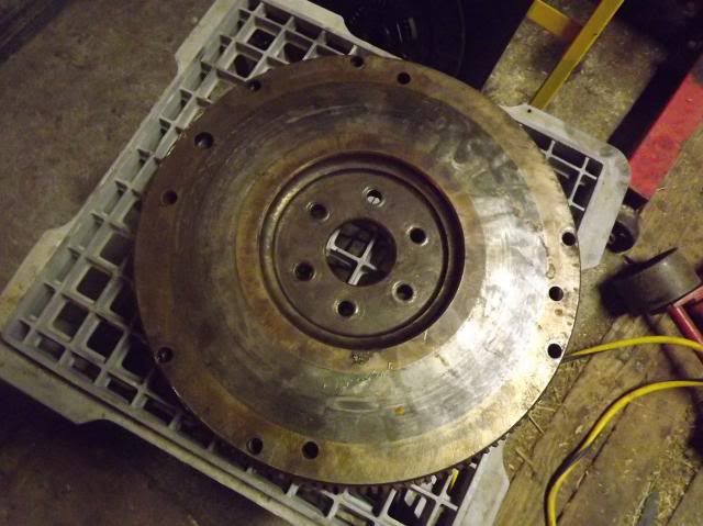
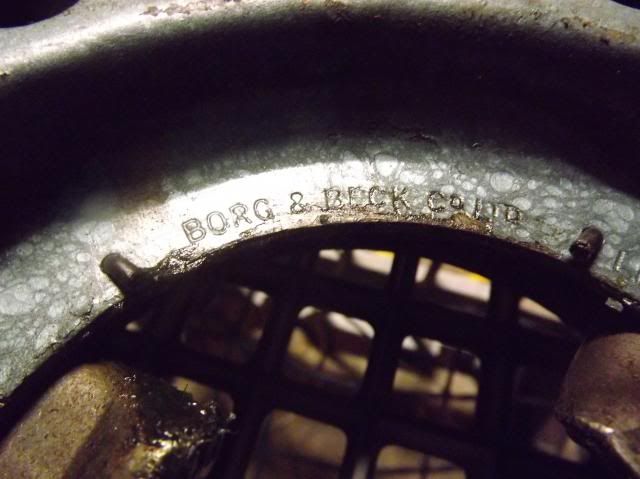
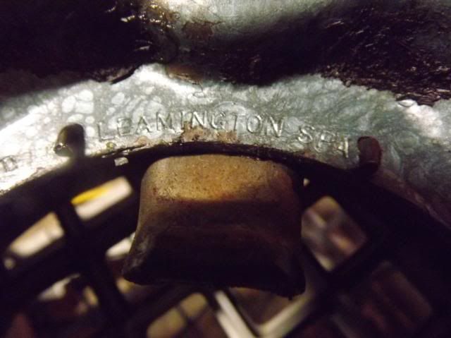
    Alrighty here are pic's of the both Landie and Holden clutch and pressure plate.
    Landie first.
    [IMG][/IMG] [IMG][/IMG]
    [IMG][/IMG] [IMG][/IMG]

    Holden fly wheel re-drilled to suit Landie pressure plate, notice how close to the edge the holes have been drilled.
    [IMG][/IMG]
    [IMG][/IMG] [IMG][/IMG]
    [IMG][/IMG]

  10. #20
    Join Date
    Jan 1970
    Location
    Irymple, Victoria, Australia
    Posts
    2,902
    Total Downloaded
    0
    Thanks Chris,
    very interesting pics, the new holes are drilled very close to the outer edge. Were they drilled right through so that the bolts butted up against the ring gear?

    Cheers, Mick.
    1974 S3 88 Holden 186.
    1971 S2A 88
    1971 S2A 109 6 cyl. tray back.
    1964 S2A 88 "Starfire Four" engine!
    1972 S3 88 x 2
    1959 S2 88 ARN 111-014
    1959 S2 88 ARN 111-556
    1988 Perentie 110 FFR ARN 48-728 steering now KLR PAS!
    REMLR 88
    1969 BSA Bantam B175

Page 2 of 3 FirstFirst 123 LastLast

Bookmarks

Bookmarks

Posting Permissions

  • You may not post new threads
  • You may not post replies
  • You may not post attachments
  • You may not edit your posts
  •  
Search AULRO.com ONLY!
Search All the Web!