

 Reply With Quote
Hi Graeme,Originally Posted by Graeme

Pardon me not keeping up with your adventures, but what have you used/done with those up/down-shift wires? A link so as to not get too far off-topic would be good please!
Regards,
Les.

 Swaggie
I temporarily unplugged the connector and re-routed it out of the way, where it just sits without any restraint. BTW, that cable runs to the gearbox and is from where I've picked-up the up-shift and down-shift wires.
MY21.5 L405 D350 Vogue SE with 19s. Produce LLAMS for LR/RR, Jeep GC/Dodge Ram
VK2HFG and APRS W1 digi, RTK base station using LoRa
Master
Hi Graeme,
Pardon me not keeping up with your adventures, but what have you used/done with those up/down-shift wires? A link so as to not get too far off-topic would be good please!
Regards,
Les.
Swaggie
Gearshift by remote control...
http://www.aulro.com/afvb/d3-d4-rrs/...-switches.html
MY21.5 L405 D350 Vogue SE with 19s. Produce LLAMS for LR/RR, Jeep GC/Dodge Ram
VK2HFG and APRS W1 digi, RTK base station using LoRa
Swaggie
SubscriberFor those that might like two auxillary batteries in their D4.
Found here
Discowhites new NEW LXOB
Baz.
Cheers Baz.
2011 Discovery 4 SE 2.7L Kerrys
1990 Perentie FFR EX Aust Army
1967 Series IIa 109 (Farm Truck)
2007 BMW R1200GS
1979 BMW R80/7 (Scrambler project)
1983 BMW R100TIC Ex ACT Police
1994 Yamaha XT225 Serow, Kerrys
ForumSage
So with the assistance of this great thread, I set about clearing the spare battery box on my D4. ( I intend to mount my compressor in front on the primary battery.)
All is looking good, nearly ready for the Traxide kit I ordered earlier this week.
[IMG][/IMG]
- (I am waiting until I get My USI-160 before I work out exactly where to locate the glow unit.)
The following two comments got me pondering sealing the transmission computer:
I have some of the same self fusing Silicon tape.
Do people still recommend it?... Do I just wrap the actual aluminium box - should I tape the wiring too (effectively taping the plugs in?)
Thoughts?....
Mark
Of all the things I've lost, I miss my mind the most
2015 TDV6 D4.... the latest project... Llams, Traxide, Icom 455, Tuffant Kimberleys and Mofos.... so far.
2012 SDV6 SE D4 with some stuff... gone...
2003 D2a TD5...gone...
2000 D2 V8...gone...
https://bymark.photography
Master
I used this thread for inspiration when considering options for the dual battery setup. Moving to the D4 from a D3 I was disappointed to find the nice clear 'battery box' on the R/H side was now full of transfer case ECU and wiring looms.
Where I went in a different direction was that I figured I could maintain the improved protection (from dust/water) that the new location and housing of the transfer case ECU has in the D4. This is for a 2010 2.7L, if you have a 3.0L or later model you probably have more gubbins to move, not sure how well this approach works then.
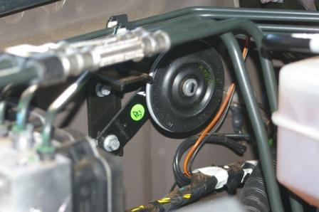
I relocated the alarm horn over to the firewall near the penetration you will use to run your wiring back into the cabin (sorry no picture).
Junked the bracket, which in mine was actually crushing the wiring to the horn and had exposed the wiring....
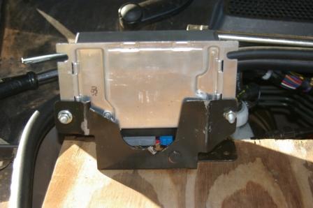
Remove the mounting bracket for the ABS solenoid block, file away the three holes for the mounting studs so that you are able to move the complete assembly a couple of mm closer to the side (gives you clearance for the battery clamp bolt later). Add a nut to each of the mounting stud to lift the solenoid block about 10mm higher (gives you clearance under the brake lines for the ECU). Leave the solenoid block hanging free for now so you can more easily get the ECU in place.
Grab your various hacksaws, dremels, files and drills and get destructive.
From the attachments you should be able to work out what to hack off, sorry I took the pictures after doing the nastiness.
Carve off all the extra ears plus the original 'shelf' section that the ECU sits against and shorten by about...... that much (you will work it out), you also need another mounting hole to pick up an existing threaded insert in the tray (again, you will work it out), remember to open up the hole so you can add a metal insert so to prevent the plastic bracket being crushed if you tighten too much.
You will also need to remove some tabs from the side of the plastic ECU cover, it will be obvious what you need to do.
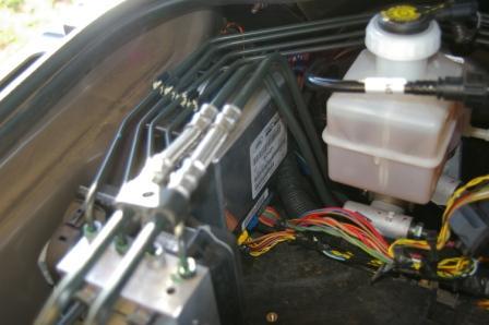
Reroute the ECU wiring whichever way works for you, I tried a few different arrangements, settled on over the top of the master cylinder and some excess length down into the blind depths below.
The next bit is where the swearing might start, you have to assemble the ECU into the modified bracket and cover, with the wiring plugged in, then slide the assembly into place and bolt it down. I did it 3 times in total during this process, you should be able to reduce that by at least 1.
Refit the solenoid block, fit the battery isolator (Traxide, what else), throw in the battery (low profile post clamps recommended), battery clamp and wiring.
Tight fit, but a fit that in my opinion is superior to mounting a battery in front of the starting battery. Plus my compressor still fits neatly in front of the main starting battery (just like a D3).
I still need to tidy up a little, maybe a couple of cable ties here and there, plus I have to add a circuit breaker for my under bonnet Anderson connector.
Master
Thanks for this excellent thread. In conjunction with this thread: http://www.aulro.com/afvb/d3-d4-rrs/...ide-setup.html I'm considering either putting an ARB compressor in this driver's side battery box or moving my second battery to this box and installing the compressor in front of the battery on the passenger side. Leaning toward latter option as compressor will get more ventilation and I've heard these in particular run quite hot.
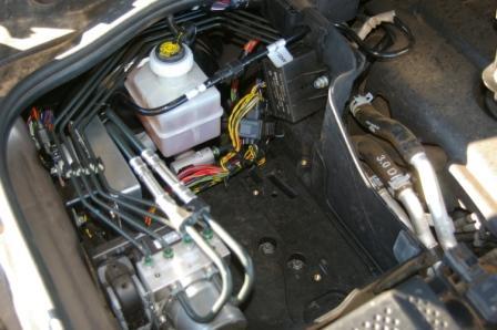
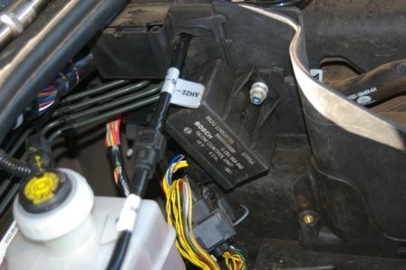
Just a quick question, more for curiosity than anything else. As per pic below my driver's side battery box seems to only have these connectors, not the mentioned ECU - this makes it easier to clear which is good.
I did buy it used (6 months old) so previous owner may have changed something but seems reasonably unlikely since the connectors are still in place and nothing has been installed in there. Is this normal? With just those connectors moved out of the way will the battery (Optima D34) just slide in with a D3 hold down to keep it in place?
Thanks,
David

Everything is easy when someone else is doing it
MY14 SDV6 SE Corris Grey
Compomotive 18s : D697s : Traxide DBS : LLAMS : ARB compressor : IC-455
Rhino Platform : GOE compressor, Tx & front bash plates, deluxe sliders
 OldBushie
Hi David, first off, be careful of fitting the battery in the driver's side battery compartment in late model D4s.
In some it can be done quite simply, while in other it can not be done because the battery can not be secured in place.
The problem is that the mounting thread for the battery hold down bolt can be partially obscured by the ABS unit.
This looks to be the case in your photo, so check first before you try to move things about.
No matter what you decide, you can clear the compartment by first rotating the large black plug and socket and then lifting it out of the base and then it and the green plug and socket can be moved out of the way.
There is also a bracket towards the back of the compartment, on the engine side, which is held in place with a single bolt.
You can remove the bold and digard the bracket.
Master
Thanks for the detailed reply Tim. Much appreciated. I'll check that.
David
Everything is easy when someone else is doing it
MY14 SDV6 SE Corris Grey
Compomotive 18s : D697s : Traxide DBS : LLAMS : ARB compressor : IC-455
Rhino Platform : GOE compressor, Tx & front bash plates, deluxe sliders
Master
SupporterHi All,
I used Graeme's excellent guide to clearing the tray and now have installed the ARB compressor I had sitting in its carry case for sometime - very happy with the result although wish I had smaller less FAT fingers as it was an effort securing the compressor bracket to the baseplate with the screws in very awkward positions")
 Posting Permissions
| Search AULRO.com ONLY! |
Search All the Web! |
|---|
|
|
|


Bookmarks