

 Reply With Quote
Thanks Remy. I'd have all the parts in my electronics workshop. I'm just getting to lazy to build stuff any more.

 Master
Hi Ron,
Clarion in a 95 model. About $30 for resistors, wire blocks and board from Jaycar.
Cheers,
Remy
Major part of the heart and soul of AULRO.comThanks Remy. I'd have all the parts in my electronics workshop. I'm just getting to lazy to build stuff any more.
Ron B.
VK2OTC
2003 L322 Range Rover Vogue 4.4 V8 Auto
2007 Yamaha XJR1300
Previous: 1983, 1986 RRC; 1995, 1996 P38A; 1995 Disco1; 1984 V8 County 110; Series IIA
RIP Bucko - Riding on Forever
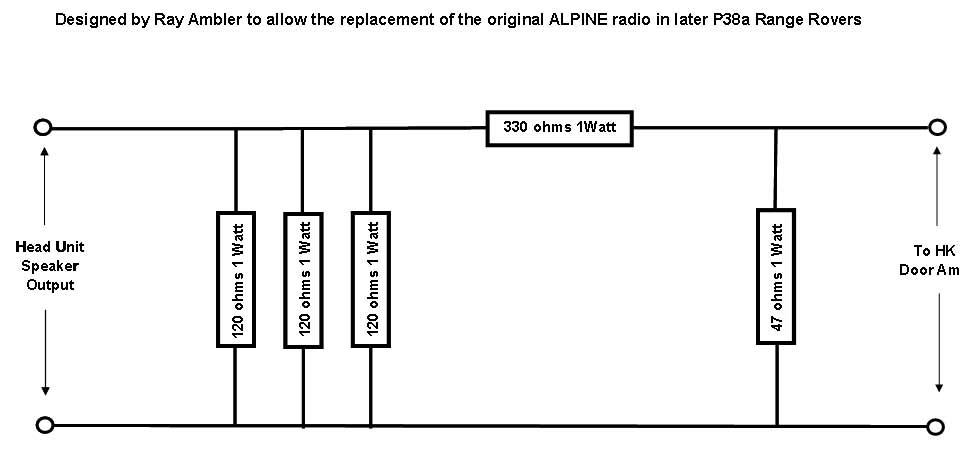
Major part of the heart and soul of AULRO.comNot really. When I first sketched it I thought it was an L-pad - then I realised I had drawn it the wrong way about. The revised sketch is attached.Originally Posted by 996TURBO

At first glance it doesn't make sense unless the negative lead into the door amps is grounded (it probably is).
The Clarion's output spec is 0,125v at 660 ohm impedance. My new HU has a 4 volt line output level.
Ron B.
VK2OTC
2003 L322 Range Rover Vogue 4.4 V8 Auto
2007 Yamaha XJR1300
Previous: 1983, 1986 RRC; 1995, 1996 P38A; 1995 Disco1; 1984 V8 County 110; Series IIA
RIP Bucko - Riding on Forever
Master
That thread is awesome. It's a team project
I'll wire Ray's attenuator this evening. Already have everything except one missing resistance.
Major part of the heart and soul of AULRO.comRevised diagram (correct way around) now uploaded.
I'm no design engineer so I'm thinking out loud here.....
It looks to me that it's not a true attentuator. It's not an L-pad (voltage divider) nor a T-attenuator (I'd expect the 1 uF cap to have low impedance to AF). I think the 750 ohm resistor is just a load resistor to match the output impedance of the head unit.
Of course, the two resistors could form part of a Pi network if the inputs of the door amps have a resistor to ground.
I wonder what would happen if I changed the values of the resistors?
What I find interesting on mine is that if I plug all RCA plugs except the front left, the buzz isn't too bad. It's still there but at much lower level. As soon as i plug in the FL channel, the buzz is very annoying.
Ron B.
VK2OTC
2003 L322 Range Rover Vogue 4.4 V8 Auto
2007 Yamaha XJR1300
Previous: 1983, 1986 RRC; 1995, 1996 P38A; 1995 Disco1; 1984 V8 County 110; Series IIA
RIP Bucko - Riding on Forever
Major part of the heart and soul of AULRO.comI haven't had a chance to play today except for trialling a 4K7 resistor directly from the HU RCA to the output lead to the door amp.
That significantly reduced the buzz to an almost inaudible level. I think I need to experiment a bit here. It also reduced the audio level but not a lot.
Ron B.
VK2OTC
2003 L322 Range Rover Vogue 4.4 V8 Auto
2007 Yamaha XJR1300
Previous: 1983, 1986 RRC; 1995, 1996 P38A; 1995 Disco1; 1984 V8 County 110; Series IIA
RIP Bucko - Riding on Forever
Master
I wired the Ray's attenuator and i have excellent results, no more buzz noise and lot of power but i may have miss the wiring of the plugs since i get sounds only on left hand front speaker...
I'll do it again more neatly.
Major part of the heart and soul of AULRO.comRay's circuit is based on using the speaker outputs from the HU not the line level (RCA) outputs. Is that where you connected it?
Ron B.
VK2OTC
2003 L322 Range Rover Vogue 4.4 V8 Auto
2007 Yamaha XJR1300
Previous: 1983, 1986 RRC; 1995, 1996 P38A; 1995 Disco1; 1984 V8 County 110; Series IIA
RIP Bucko - Riding on Forever
Master
Rewired it neater and it works perfectly. Sound on all speakers (except my rear left door that has green wires), no buzz at all. My HU is awesome with it's built in phone kit.
I did respect all Ray's infos ie i used the speakers output from the HU no RCA at all, except for the Subwoofer (SW).
I didn't use at all the Nexxia thing since i'll send it back.
I didn't count how many hours i spent on that project. Are those guys professional or what?
But now, i really think about factory making some kits and offer those on the market for people who don't want to worry about soldering.
I used a set of ISO8 (male and female), i shaped the female connector to work with the factory ISO10 pink plug. Couldn't wait for a true ISO10 female connector.
Didn't connect the S/W since i need to find a RCA connector with 2 wires to connect to the S/W RCA output on my HU.
Master
Hi Ron,
Does the RCA sub out has a the same circuit as the others?
BTW, had nexxia on phone today and they're ok for refund so i need to find a solution to make that sub work. Not that it is really necessary with the grunt the new headunit has but i don't want to carry a sub that doesn't knock
Good day
Flo
 Posting Permissions
| Search AULRO.com ONLY! |
Search All the Web! |
|---|
|
|
|

")
Bookmarks