
")

 Reply With Quote
Sorry Dave - I've just removed the reference so it doesn't cause any confusion.Originally Posted by Blknight.aus

Steve

 RoverLord
your interpretaition of my terminology is abit off.
the main box is the main box
the leg is the bit that holds the Tcase geards
the Foot is the bit that holds the diff.
Dave
"In a Landrover the other vehicle is your crumple zone."
For spelling call Rogets, for mechanicing call me.
Fozzy, 2.25D SIII Ex DCA Ute
TdiautoManual d1 (gave it to the Mupion)
Archaeoptersix 1990 6x6 dual cab(This things staying)
If you've benefited from one or more of my posts please remember, your taxes paid for my skill sets, I'm just trying to make sure you get your monies worth.
If you think you're in front on the deal, pay it forwards.
TopicToaster
SubscriberSorry Dave - I've just removed the reference so it doesn't cause any confusion.
Steve
TopicToaster
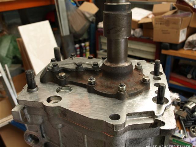
SubscriberThe front bearing plate and layshaft can now be assembled into the case.
You need to assemble the layshaft and bearing plate together before attempting to put them into the case. I put the layshaft in a vice, offered up the bearing plate on a bit of an angle and with a bit of wriggling got the input and layshaft gears to mesh and the layshaft to seat into the bearing cup.
You then lower the plate/layshaft assembly into the case. I found it helpful to have a helper at this stage as I just didn't seem to have enough hands to hold it all together and lower it in gently.
Fit the two large locating dowels, and the studs. The top 2 studs need to have some loctite/sealant on them when fitted as their holes go right through into the case.
You cant fit the bellhousing yet as the selector shafts have to go in first, so I temporarily used nuts and large thick washers to hold the front plate on until the selectors are fitted.
Fit the oil pump, gasket and cover plate:
Make sure the cover plate is flat. If its not you can use some medium wet and dry paper on a sheet of glass to get it flat.
If the oil pump you are using has a steel shaft, the shorter square end goes into the pump gear, and the longer end goes into the layshaft.
Before you fit the oil pump cover, make sure that the the oil pump turns smoothly when you turn the mainshaft.
I used some thread lock on the oil pump cover bolts as they are known for coming loose. The ones on this particular box were not much more than finger tight when I pulled it apart.
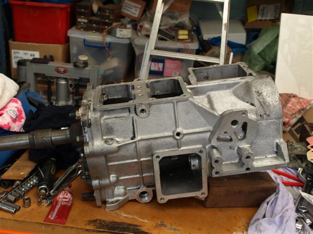
At this point I laid the box down again so I could continue to fit the reverse gear/shaft and the selectors.
Steve
RoverLord
depending on the type of gasket you're using dont forget to apply a sealant to the gaskets prior to the final assembly.
I use hylomar #3 (or one of the many vairents thereof)
paint the gasket with the stuff and let it sit for at least half an hour so the goop can seep into the paper. Another point that hasnt been covered yet (and the oil pump reminded me) is to "paint" all the surfaces of the steel bits with oil as you assemble the box to help prevent rust and to provide initial lubrication.
Dont be shy with the application of the oil on the pump gears themselves as this aids the initial prime up of the pump.
its also a prudent idea to check trueness of the mating of the faces of the pump housing and cover plate without the gaskets or the internal parts fitted especially if you suspect that you have had an oil leak there previously.
Dave
"In a Landrover the other vehicle is your crumple zone."
For spelling call Rogets, for mechanicing call me.
Fozzy, 2.25D SIII Ex DCA Ute
TdiautoManual d1 (gave it to the Mupion)
Archaeoptersix 1990 6x6 dual cab(This things staying)
If you've benefited from one or more of my posts please remember, your taxes paid for my skill sets, I'm just trying to make sure you get your monies worth.
If you think you're in front on the deal, pay it forwards.
TopicToaster
You then lower the plate/layshaft assembly into the case. I found it helpful to have a helper at this stage as I just didn't seem to have enough hands to hold it all together and lower it in gently.
If you remove the layshaft bearing cup from the front cover plate it makes it a bit easier to fit it all together but don't forget to refit it (and the shim) after you have it all together.
Cheers......Brian
1985 110 V8 County
1998 110 Perentie GS Cargo 6X6 ARN 202516 (Brutus)
TopicToaster
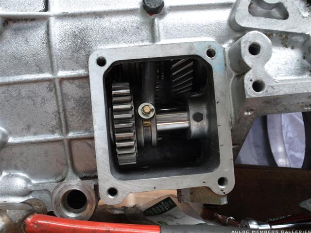
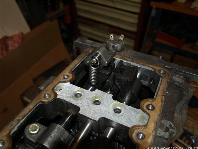
SubscriberFit a new O-ring to the reverse gear shaft, and insert the shaft into the case and through the gear (selector slot on the gear is towards the rear of the box).
The reverse gear o-ring is a known leak area between the transfer and main boxes, so I used a bit of loctite sealant to seal between the shaft and the case. To get the loctite in there without ending up with it in the reverse gear bearing, I just pushed the shaft in slightly past where it needed to sit, applied sealant around the rear end of the shaft and pulled the shaft back into place. This made sure the sealant was around the shaft.
Loctite is also required on the retaining bolt threads.
This photo shows the shaft and gear fitted.
You cant actually fit the selector arm until the selector shafts are in the box - which is the next step.
Steve
TopicToaster
SubscriberTime to fit the selectors.
The manual is quite clear on the assembly order, orientation and adjustment of the various parts so I wont repeat that info.
A few useful hints from my limited experience :
- Don't refit the old roll pins - new ones are cheap to buy and definitely have more grip than the old ones.
- mark the position of the selector forks along each shaft before sliding them into the box. Makes it a lot easier to try and line up the holes to drive the roll pins into the shaft
- there are 2 interlock plungers that go between the center and outer shafts (one on each side of the center shaft), and an additional smaller diameter one that goes through the center shaft. This isn't very clear in the manual.
- you must keep the fitted shaft(s) perfectly in neutral position while you fit the next shaft, or the interlock will prevent you getting the next shaft in.
- as well as following the assembly order closely, sit all the shafts, forks etc in place (including reverse) before finally driving the roll pins home (rather than fitting one shaft and its forks at a time). Otherwise you'll likely find you have a part that you cant get into place without pulling it all apart again.
- the spring loaded gate on the reverse selector is much easier to fit the spring to if you open it right up and rest it against the top of the case. Fti the spring onto the shaft, then onto the gate. Once the spring is on, just flip it over into position.
The reverse selector arm can now be fitted. The lockwired bolt that is threaded into the case also screws into the selector.
You want to get as much engagement of the selector foot as you can without the selector foot being too tight against the gear.
I found the easiest way to adjust it was to hold the selector against the gear, screw the bolt in until it touched, then back it off until it engages the thread. From there just tighten it up until the bolt is tight against the case.
Once you are happy with the adjustment, undo the bolt a couple of turns (without going too far and dropping the selector arm off the end) and apply some thread lock and tighten it up again.
Here's a couple of photos that were actually taken during disassembly, but they show how everything should end up.
The detent balls and springs can now be fitted and the selector cover and gasket bolted in place. The reverse spring is different to the other two (heavier spring according to the manual).
The reverse gear cover can also be fitted. Don't forget to lockwire the pivot bolt to prevent it turning.
At this stage I also fitted the reverse gear switch and the gear lever (temporarily), then made sure I could select all gears and the switch worked correctly (on when reverse selected).
Steve
Wizard
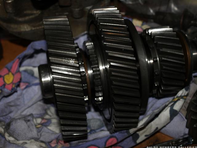
Steve, before you get back to the transfercase, would you mind taking a 3/4 front on photo of the range change hub on the intermediate gear and the high range gear ? Jumping out of high range, sometimes violently enough to jump straight into low range is not uncommon, so wear diagnosis of these components and various solutions to the issue probably should be discussed here.
Wagoo.
TopicToaster
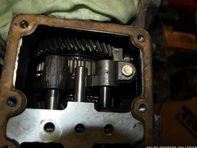
SubscriberNo problem.
Here's a general photo - give me some feedback on what we're interested in and I'll take some better ones.
Steve
Wizard
Thanks Steve. Looking for tapered wear on the male and female dog teeth on the range selector and high gear. LandRover in there infinite wisdom always deleted every second male dog tooth, and shortened every second female one.What this means is when you change from low back into high range you have a 50/50 chance of engaging a short female tooth.Depending on how many kms the vehicle is driven on the shorter teeth this can promote relatively rapid tapered wear on both male and female teeth.
Maxidrive used to offer a Bronze thrust washer set of different thicknesses so that you could get more dog tooth engagement in high and low range my moving the high and low range gears closer to the range change hub. I've used these with some success, but i've also done other things to address the problem that i probably shouldn't go into here on a straight overhaul thread.
Wagoo.
 Posting Permissions
| Search AULRO.com ONLY! |
Search All the Web! |
|---|
|
|
|
Bookmarks