Page 1 of 2 12 LastLast
Results 1 to 10 of 14

Thread: How to rebuild a TD5 Engine

  1. #1
    Join Date
    Sep 2007
    Location
    Gold Coast
    Posts
    6,078
    Total Downloaded
    0

    How to rebuild a TD5 Engine

    Note - If you do this, ensure you follow the workshop manual. This is a step by step of the main points that I took pics off when I did it... there may be errors or ommisions!!

    Thought it may be worth putting up a thread showing the total steps involved in rebuilding a TD5 engine. This is the one I found the bent conrod in.

    It is out of a 2003 D2A manual with 216k km on the clock
    Very low compression readings were the catalyst to pull the engine – 150-165psi

    So the engine came out.


    I then stripped it down - the head came off before I removed it as I managed to damage one of the bell housing bolt heads.
    Here is one of the reasons for the low compression.


    I won’t waste time with pictures of the strip down

    So the first step was to get the pistons and block to a machine shop.
    I had the block machined to suit a new genuine set of 20 thou Kolben Schmitt pistons. The clearance specified by the workshop manual and the engine shops computer system specified 7-8 thou clearance which seems like quite a bit, but with nothing to contradict this we went for 7thou clearance.


    Building up the pistons on the rods. The rods are crack fractured so the caps can really only go on one way around. Arrow on piston and lug on rod both need to point to front of engine:


    Fitting replacement main bearing shells into block:


    New Thrusts fitted to main number 3:


    Crank re-fitted:


    Checking thrusts are still in place:


    Main bearing shells in cap:


    Fit and tighten main bearings:


    Crank end float now needs to be checked. I used a padded lever and some feeler gauges. manual shows a DTI but I didn't have one to hand.
    Oil squirter for timing chain refitted:


    Fit oil squirters for each piston:


    Assemble new rods and pistons:


    Fit pistons in block after arranging ring gaps as specified. (120degrees apart and not on the thrust side)


    Here you can see the oil squirter hitting the cut out in the piston:


    Checking piston protrusion on all 5 to decide on headgasket- In this case we went for the thinnest gasket:


    Took apart oil pump to check clearances – feeler gauge between parts to decide:


    Fit oil pump assembly with metal seal, and pickup:


    Fitting oil pump drive gears and chain.


    Fitting tensioner guides:


    Fit timing chain to corresponding marks:


    The fan bearing in the timing cover sounds pretty rough so I decided to change it:


    Spigot fitted to new bearing:


    Timing cover with bearing fitted to block:


    Next I decided to do the head. I firstly stripped it completely, and cleaned it up. It was skimmed, and pressure tested. - when stripping the head, the pedestals, rockers, and lash adjsuters should be kept in order, and the lash adjusters should be kept upright


    2 of the valves looked a bit dodgy so I got an entire new set.
    Then spent about 4 hours lapping them in:


    Clean the main head again to remove any lapping paste residue, and build up with valves and new stem seals etc:


    Fit lash adjusters:


    Fit injector pedestals:


    Fit roller rockers:


    Oil cam journals and lower in camshaft, then apply sealant to the mating face on the other half of the head:


    Fit and torque up the top half of the head, including with the rocker shaft bolts -will need to remove this to fit injectors later on.


    Fit headgasket and dowels to block (Went for 2hole gasket (thinnest based on 14thou piston protrusion)


    lower head on:


    Torque head up in the 5 specified stages:


    Fit new exhaust manifold gasket and manifold:


    Fit inlet manifold gasket and fuel inlet filer:


    Then oring that holds in filter:


    Fit fuel regulator, return line, and inlet manifold:


    Lift cam pulley and timing chain onto front of cam - timing mark between coloured links:


    Here you can see the adjustment available:


    Bolt that locks the cam in position when you do this:


    Fit cam chain tensioner and then tightened up cam pulley, then fitted front plug and removed locking pin


    Injectors fitted with rocker shaft. Bump clearances need to be set now on the injectors. rotate cam to full lift, screw down adjuster screw to bottom injector pump, then back off one turn. tighten lock nut.


    Exhaust manifold fitted - not shown before:


    Fit the 4 glow plugs to cylinders 1-4


    Alternator and tensioner


    Injector loom


    Rocker cover:


    Solid Flywheel and uprated clutch:


    Sump and rear main were then fitted.

    Final tightening of front pulley to 340lb/ft next.

    Fitting engine:


    Plumbing and wiring:


    Once it was all plumed, I pulled the fuel pump fuse, turned it over till it got oil pressure, then put the fuse back in, primed it and it started first go.

    Finished:


  2. #2
    Join Date
    Jan 1970
    Location
    Moruya Heads/Sth. Coast, NSW
    Posts
    6,532
    Total Downloaded
    0
    Very good pictorial, I'd like to suggest a few tips for anyone contemplating a rebuild, it applies to all diesel engines.
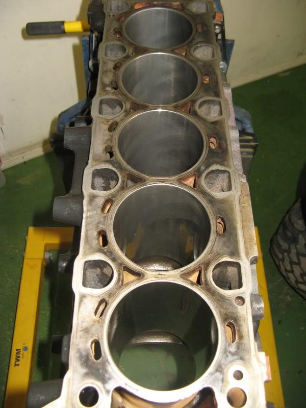
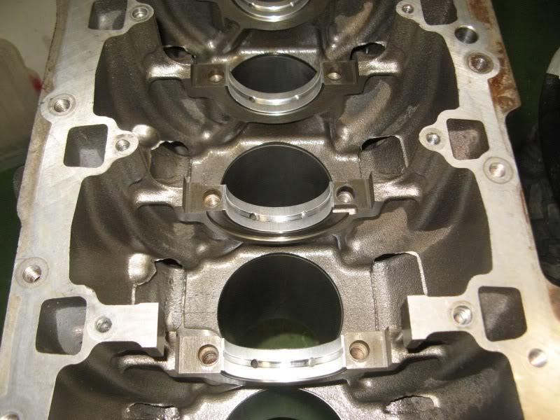
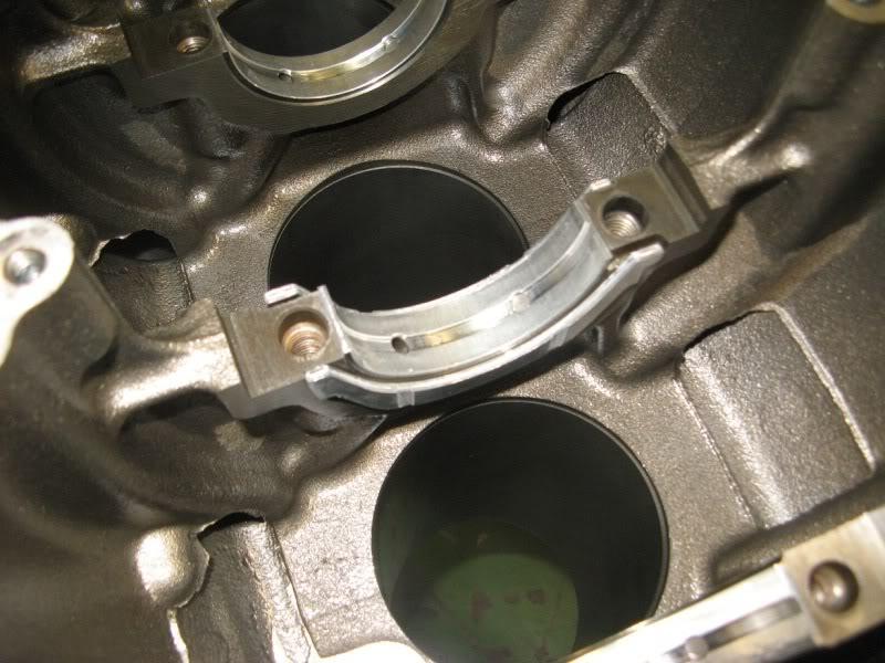
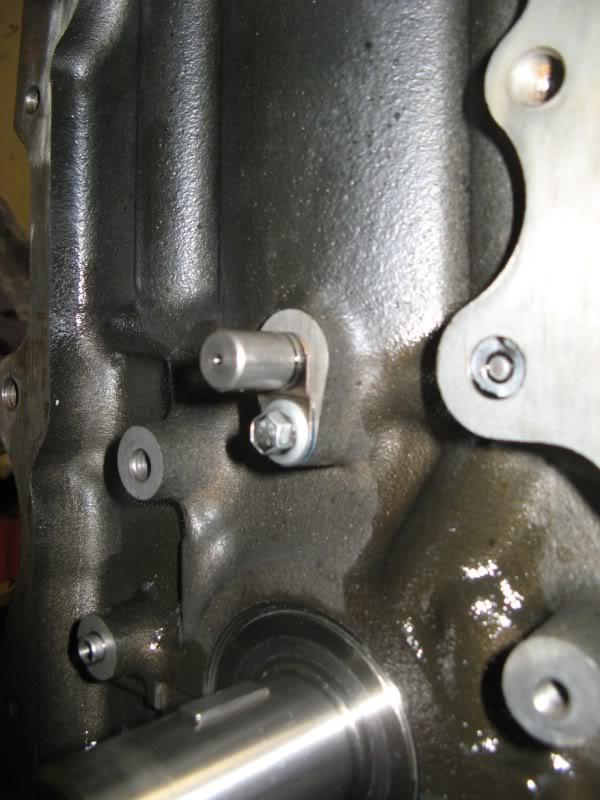
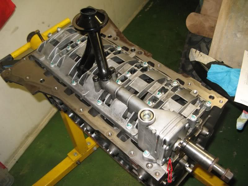
    It is good practice to remove all the casting flash in the sump area of the block, there was a fair bit of it in this engine, a small die grinder and a couple of hours will prevent any damage from bits of flashing breaking off.
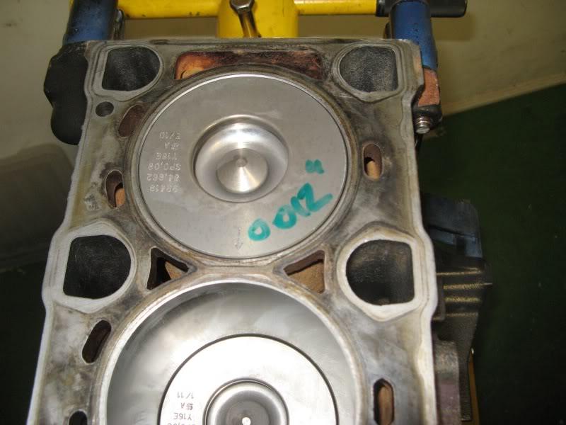
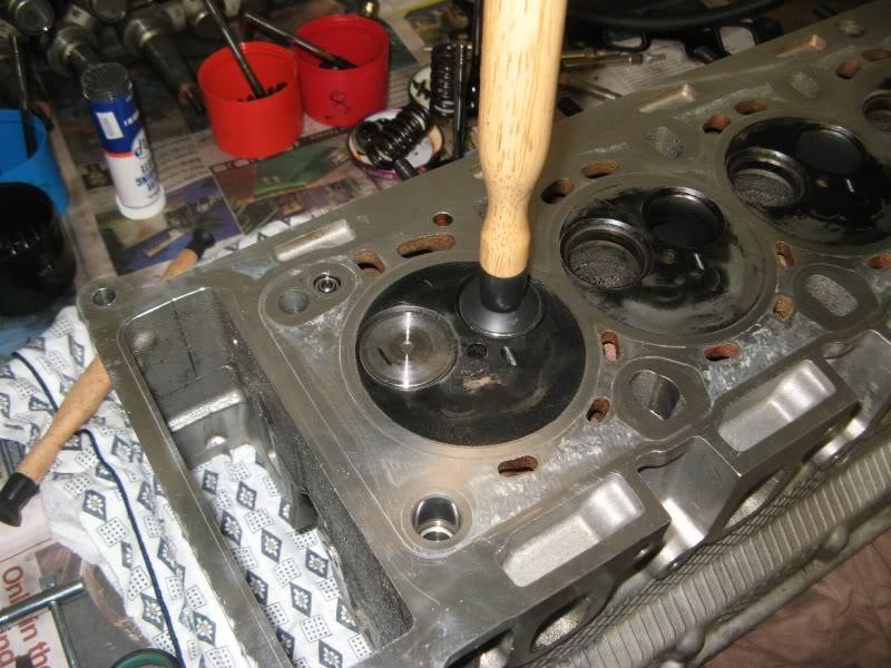
    If you have the head skimmed the machinist needs to recess the valves into the head to maintain clearance.
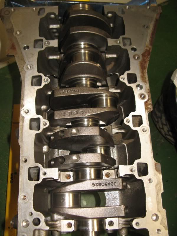
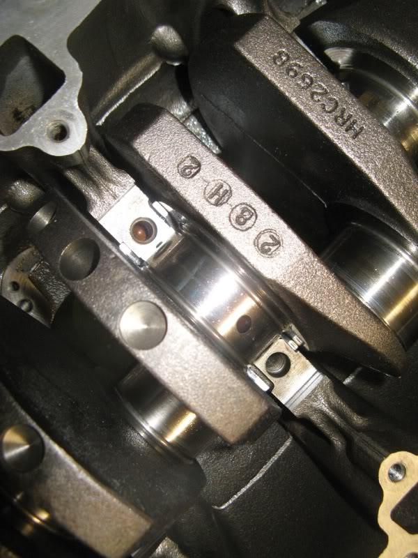
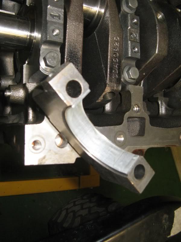
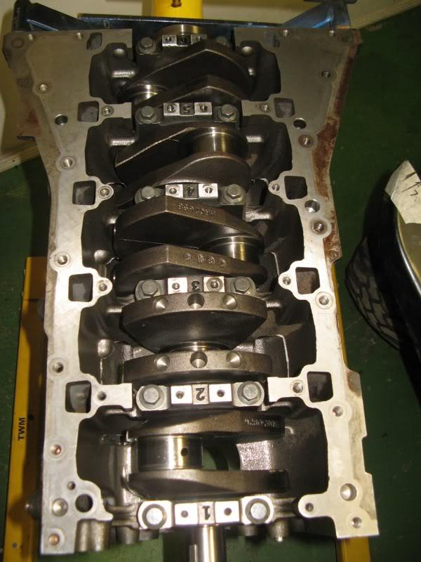
    It is also good practice to Plastigage the crank journals to check for correct clearnces and if the crank is ground undersize make sure the machinist maintains the journal fillets to factory specs.,
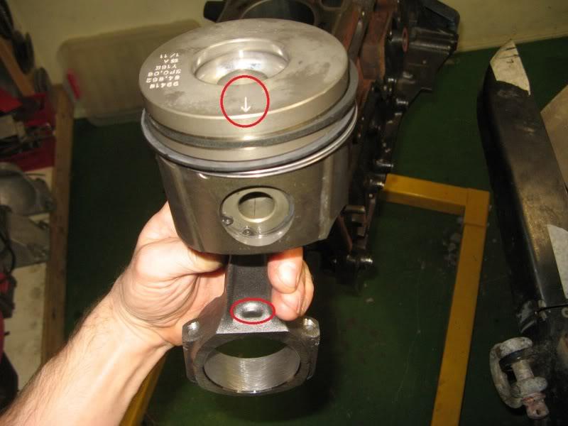
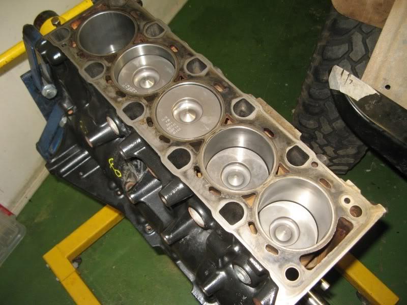
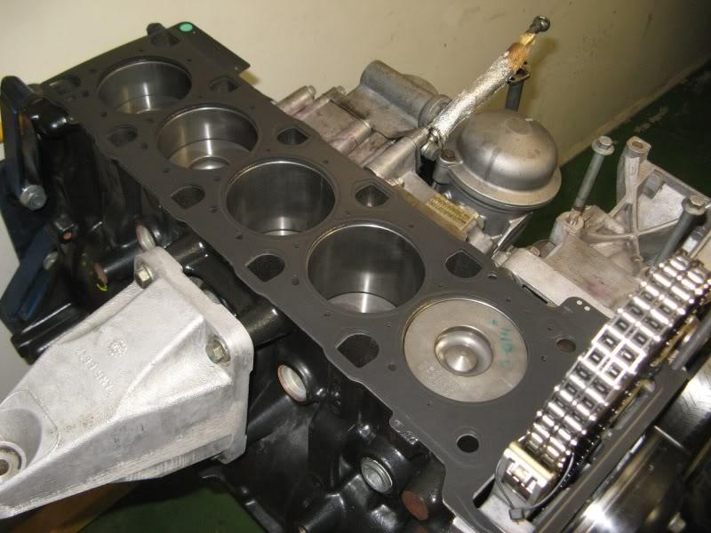
    Always bore fit new rings to their bores and check ring gaps, do not rely on the sizes printed on the ring packaging/brochure, better to be sure, Regards Frank.

  3. #3
    Join Date
    Sep 2007
    Location
    Gold Coast
    Posts
    6,078
    Total Downloaded
    0
    Yep good points, my thread wasn't that detailed! If you attempt this it needs to be done with the workshop manual!!

    The recessing of the valves wasn't necessary in this case, and hasnt been on any td5 head I have been involved in skimming.

    The crank was in spec in terms of journal diamater.

    The removing of flashing isn't a bad idea, but I didn't do that.

    edited to add,

    p.s its now done about 1500km since being built with no issues (apart from a leaing pwersteering pump which I have replaced with a new one)
    p.p.s a genuine ps pump from a main LR dealer is 50$ cheaper than the cheapest aftermarket pump on ebay

  4. #4
    Join Date
    Jan 1970
    Location
    Moruya Heads/Sth. Coast, NSW
    Posts
    6,532
    Total Downloaded
    0
    I noticed there are no locating tangs on any of the bearing shells (mains and big ends), are they located by pins through the shells, Regards Frank.

  5. #5
    Join Date
    Sep 2007
    Location
    Gold Coast
    Posts
    6,078
    Total Downloaded
    0
    Hi Frank,

    No there isnt any form or locating tab or pin on them, mains or big ends.

    cheers
    Pete

  6. #6
    Join Date
    Aug 2009
    Location
    Engadine - In the Shire, 1 hr South of Sydney
    Posts
    2,050
    Total Downloaded
    0
    Excellent presentation Pete, now to go get that beautifully clean motor dirty, eh?

  7. #7
    Join Date
    Nov 2007
    Posts
    33
    Total Downloaded
    0
    Great heads up, what was the cost?

  8. #8
    Join Date
    Sep 2007
    Location
    Gold Coast
    Posts
    6,078
    Total Downloaded
    0
    Ok in terms of parts and costs:

    Camshaft
    Rockershaft
    Con Rods x5
    Piston assys (inc rings and pins) +.020 x5
    Main Bearing set (std)
    Big End bearing set (std)
    Big End bolt set
    Main bearing bolt set
    Thrust shims x2
    Front pulley bolt
    Timing chain kit (gears and chain)
    Timing chain guide 1
    Timing chain guide 2
    Oil pump chain kit
    Bolt oil pump gear
    Oil pump bolts short x 10
    Oil pump bolts long x 12
    Timing cover fan bearing
    TD5 Bottom end gasket set (all gaskets and seals for the block)
    Valve stem oil seal x 10
    Full set of valves
    Head Bolts x12
    Head Gasket (2 hole)
    Rocker cover gasket
    Injector seals and o rings
    rocker shaft bolts etc
    steel head dowels
    Solid flywheel and clutch.
    Thermostat
    Replacement low milage set of injectors
    3 hoses
    hoseclamps - assorted

    machine work included head pressure check clean and skim
    block rebore and hone
    Valves lapped

    It came to roughly 5k in terms of parts and machining for the above. (There were some items in there though like the solid flywheel and clutch that came to $1100 inc shipping on their own)

    I also managed to source some bargain parts, such as the new cam which came from a UK main LR dealer for under $50!

    The replacement set of injectors were second hand.

    If you want to work out the actual costs of just the normal rebuild parts, have a look at www.turnerengineering.co.uk

    cheers
    Pete.

  9. #9
    Join Date
    Jul 2011
    Location
    Yarrawonga, Vic
    Posts
    6,513
    Total Downloaded
    0
    Excellent thread filed for future reference.

    Just wondering about the cause of the bent conrod, did the engine suffer a hydraulic lock up ? or do you think it was like it when you got it.
    Surely not normal wear and tear !!

    Also a lot of talk on the forums about de-webbing the exhaust manifold, Im considering doing to mine, Notice you did not do so, I wondered if there was a reason to not deweb ??

    thanks Don

  10. #10
    Join Date
    Sep 2007
    Location
    Gold Coast
    Posts
    6,078
    Total Downloaded
    0
    Quote Originally Posted by goingbush View Post
    Excellent thread filed for future reference.

    Just wondering about the cause of the bent conrod, did the engine suffer a hydraulic lock up ? or do you think it was like it when you got it.
    Surely not normal wear and tear !!

    Also a lot of talk on the forums about de-webbing the exhaust manifold, Im considering doing to mine, Notice you did not do so, I wondered if there was a reason to not deweb ??

    thanks Don
    Hi Don,

    In all honesty it can only be fuel / water ingestion or over revving so I will pick fuel... With the really strange issues we found inside this engine I would think the damage was already done when it was purchased by the owner (its not my car)

    With regard to the webbing, I am going to go against the grain on this forum as I think it is a complete waste of time, so havent done it on either mine or this one.

    neither have suffered a broken stud atall either. I did put better qulity ones in on both however when I have had them apart.

    If either ever breaks a stud I may change my mind but at the moment it seems a waste of time imo. I definetely wouldn't ever drill out and fit larger studs which some people do either, but then others swear by it so who knows.

    cheers
    Pete

Page 1 of 2 12 LastLast

Bookmarks

Bookmarks

Posting Permissions

  • You may not post new threads
  • You may not post replies
  • You may not post attachments
  • You may not edit your posts
  •  
Search AULRO.com ONLY!
Search All the Web!