Results 1 to 6 of 6

Thread: Madman EMS2 install

  1. #1
    Join Date
    Jan 2013
    Location
    Brisbane
    Posts
    91
    Total Downloaded
    0

    Madman EMS2 install

    Well I have finally received my EMS2 gauge and a box of sensors (more sensors still to come) I plan to document my install (and hopefully my success) as a mini project right here. I'll put photos of every sensor install and the install of the EMS2 itself. I'll start by adding this picture
    Attached Images Attached Images

  2. #2
    Join Date
    Jan 1970
    Location
    Melbourne - Eastern sector
    Posts
    963
    Total Downloaded
    0
    Good work mate

    I will be watching with interest. I have had a EMS 2 for a number of years now and for the most part they do what they do very well. I have battled earthing issues which can cause erratic readouts.

    I am about to do a full re install of the EMS2 in my disco ute after i have the new TD5 engine running

    Mick

  3. #3
    Join Date
    Jan 2013
    Location
    Brisbane
    Posts
    91
    Total Downloaded
    0
    First things first, follow this at your own risk, if something doesn't look right or feel safe don't do it.
    I have taken lots of photos of each step, but not all will be posted, I will attempt to describe the steps but I may have errors.

    ASK for help if needed, I'm more than happy to help, oh and plan to do this over quite a few days, I haven't finished mine yet but I do tend to take my time.

    OK that said lets begin, I ordered the EMS2 with the TD5 kit this included the oil pressure, oil temperature, coolant temperature senders and the 60 MM EGT probe, I assume NATA had run out of the triangular coolant temp sender mount for the TD5 as I received the 36mm inline sender mount (pictures above), which I was happy to get as this has the screws for the coolant loss alarm and means I didn't have to drill into the coolant header tank (however you do have to cut your radiator hose).

    Of all the senders I have to fit I decided to fit the EGT probe first, the expected method of fitment is in a hole in the EGR blanking plate, however my EGR is still fitted (for now), and secondly this would only measure the EGT of number 1 cylinder.
    I chose to drill and tap the manifold where all cylinders meet just before the turbo, to do this you will need a drill bit 3 or 4 mm for a pilot hole and a 9mm ready for the tap (buy some new drill bits if yours are blunt), the tap size is a 1/8 NPT, this is a tapered tap and will cut a larger thread the deeper you drive it (I borrowed my NPT tap from work).

    Makin' Holes, Start with the engine cold, no point in burning yourself now is there? remove the plastic cover (if if fitted) by removing the 3 13mm bolts, once this is off you'll want to remove the heat shield from the manifold and turbo, there are 2 8mm bolts near the head and one 10mm bolt on the back of the turbo (there is an access hole in the heat shield for this), carefully remove the shield as not to bend it or catch any wires.
    On the manifold you will see a 9mm raised bump next to the turbo, this is where I drilled, Safety glasses on! don't drill right through yet, but start to drill in the centre of this bump as to leave a small dent this will help you locate the centre, now once you are ready to go with all the tools start the car and drill the first pilot hole, immediately change drill bits and drill the 9mm hole, remove all metal swarf with a brush or air gun, with the engine running all swarf should be ejected from the manifold.
    I chose to stop the engine here and tap the hole using grease on the tap to catch the swarf, I felt less pressure on myself tapping the hole without worrying about the building heat, you can tap with the engine running if you wish.

    Result:


    You can see the swarf piled up on the left between cylinders 3 and 4.

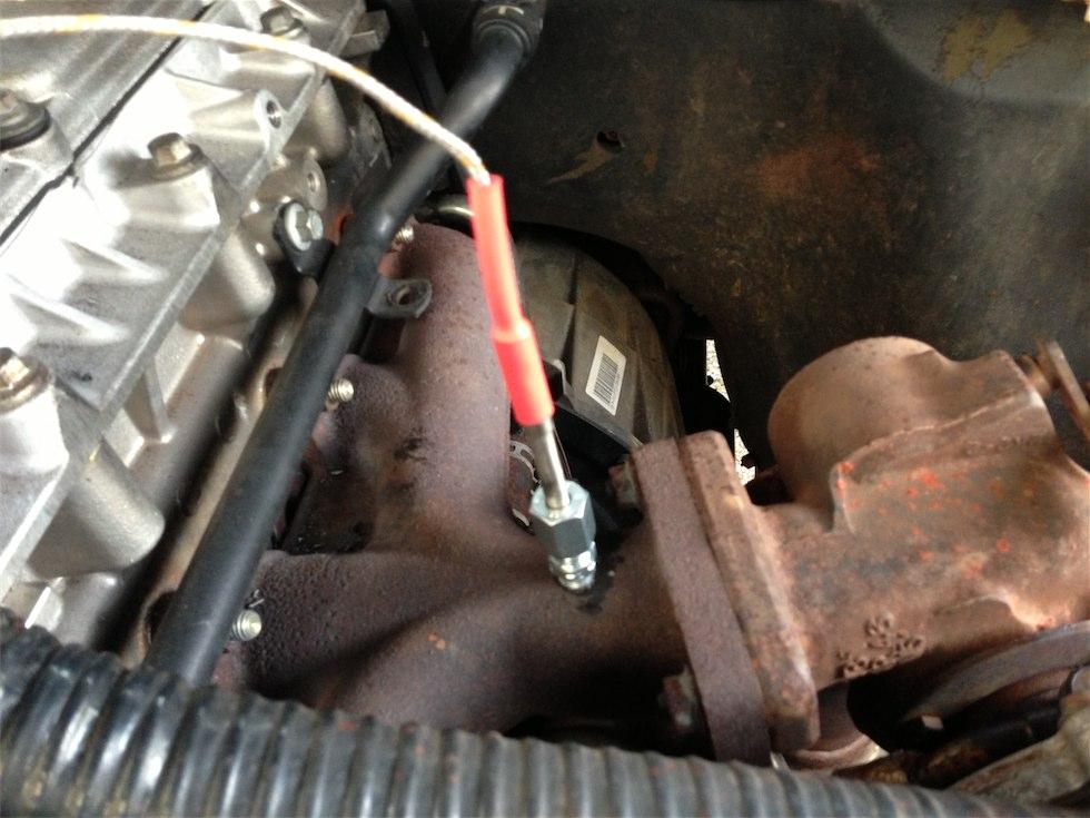
    The Thermocouple fitted:


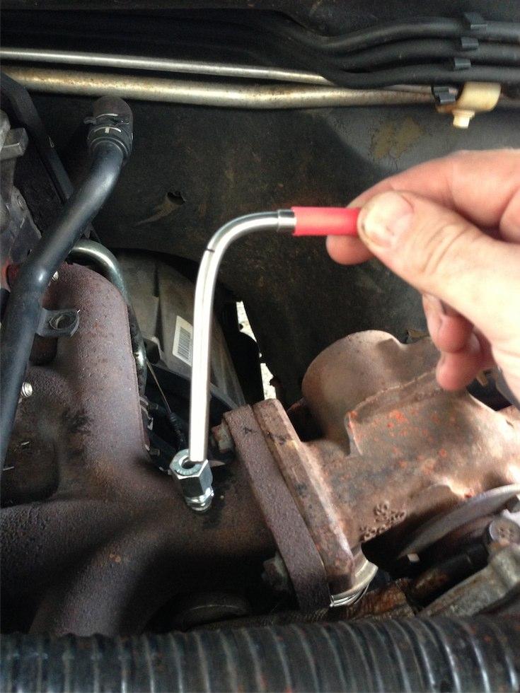
    Here I could have drilled a hole through the heat shield for the probe to come though but I didn't like that idea so I decided to reform the probe using a 12mm pipe bender to get started and then used a screwdriver with a hole through the handle to finish it off:


    More to follow...

  4. #4
    Join Date
    Nov 2010
    Location
    Murgon
    Posts
    495
    Total Downloaded
    0

    Big weekend for the EMS2

    Well done for doing a write-up of this install. I'm sure your clear narrative and photos will help others to see that there isn't much about it that's too difficult and they'll put one of these units into their vehicle.

    The weekend just gone saw me and my Dad do most of the install on my 99MY Td5. My EMS2 has only been sitting in the shed since September last year...

    I elected to go for Boost pressure, EGT, coolant Temp/low level alarm and the other temp sender will go on the transfer case.

    My tip of the day for making the drilling and tapping of the manifold less messy is to attach a couple of N45 rare earth magnets either side of where you are drilling the hole and they'll suck up that swarf very effectively. One can never have enough magnets....

    I have now got to drill my intake manifold for the boost pressure sensor and that's the bulk of the install over. The photo shows a flat area just to the left/rear of the MAP sensor (?). In this location the acoustic cover will not foul the sensor (based on my crude measuring, which, if too crude (and therefore wrong) will require me to remove some of the foam from the underside of the cover to accommodate the sensor). The cable tie is only temporary!

    I'll check back to see how it goes for you.

    FWIW I elected to put the EGT probe into the manifold on a horizontal alignment with the mid point of the manifold - I filed a flattish spot on the casting mark and drilled toward the front of the vehicle. The probe now runs pretty much parallel with that short coolant hose that sits behind the turbo. There's plenty of room to access the coolant hose if ever I need to again.
    Attached Images Attached Images

  5. #5
    Join Date
    Jan 2009
    Location
    On the road around Australia
    Posts
    900
    Total Downloaded
    0
    Off topic slightly, but has anyone who has worked with these style engine monitors ever compared temperature readings between the oil temp senders that are tapped through the gearbox or T/C housing into the oil itself, vs the thermocouple type that is just bolted onto one of the housing bolts outside the case? I've often wondered how accurate a reading the thermocouple type senders give...

    I like the idea of the EMS2, but I'm concerned that it's almost too much information for one LCD. I'm looking at making a slightly more intelligent system from an arduino board and colour LCD, that would jump straight to any readings that are out of tolerance, perhaps highlight it in big red figures. With the madman system I'm worried as to whether you can see the woods for the trees...

  6. #6
    Join Date
    Jan 2010
    Location
    Melbourne
    Posts
    1,801
    Total Downloaded
    0
    Quote Originally Posted by mike_ie View Post
    Off topic slightly, but has anyone who has worked with these style engine monitors ever compared temperature readings between the oil temp senders that are tapped through the gearbox or T/C housing into the oil itself, vs the thermocouple type that is just bolted onto one of the housing bolts outside the case? I've often wondered how accurate a reading the thermocouple type senders give...

    I like the idea of the EMS2, but I'm concerned that it's almost too much information for one LCD. I'm looking at making a slightly more intelligent system from an arduino board and colour LCD, that would jump straight to any readings that are out of tolerance, perhaps highlight it in big red figures. With the madman system I'm worried as to whether you can see the woods for the trees...
    the madman will flash any out of tolerance readings up on screen with a warning msg, flashing red led and alarm. You can clearly see all your readings on one screen, auto scroll or choose to monitor one reading. So long as all is in tolerance there's no real need to look at it - it isn't distracting. The up/down buttons on the front are easy enough to poke at whilst driving if you wanted to look at just one sender. I don't think a DIY Adruino set up is worth the time and bother unless the EMS-2 does not cover your needs.

Bookmarks

Bookmarks

Posting Permissions

  • You may not post new threads
  • You may not post replies
  • You may not post attachments
  • You may not edit your posts
  •  
Search AULRO.com ONLY!
Search All the Web!