Results 1 to 6 of 6

Thread: 4BD1 Starter Rebuild

  1. #1
    Join Date
    Sep 2008
    Location
    Geelong, VIC
    Posts
    4,442
    Total Downloaded
    0

    4BD1 Starter Rebuild

    Been a little short on shed time lately, so I took the opportunity to rebuild a couple of 4BD1 starters I had on the shelf.
    Thought others might be interested....

    Strip is pretty straightforward and I didn't take any photos.
    Remove the 2 hex head bolts through the brush cover that hold the motor on, and undo the 2 small screws that hold the cover to the brush holder.

    Remove the brush cover, then remove the motor.

    Brushes are probably quite worn unless they've been replaced previously.
    Here's the first one I pulled apart compared to a new brush:


    I got new brushes from Ashdown Ingram:


    Note that the brushes are silver soldered or similar from the factory, and aren't just plain solder. You need to cut them off then file back to get a good surface to solder to.
    Soldering on the new brushes isn't hard, but you do need to get plenty of heat into them. I used a 60W iron that struggled and only just them hot enough. An old copper plumbers soldering iron and a blowtorch might be a good option if you don't have a big electric iron.

    Here's the new ones soldered to the brush holder:


    The commutator probably needs a bit of a cleanup - like this one:


    Steve
    1985 County - Isuzu 4bd1 with HX30W turbo, LT95, 255/85-16 KM2's
    1988 120 with rust and potential
    1999 300tdi 130 single cab - "stock as bro"
    2003 D2a Td5 - the boss's daily drive

  2. #2
    Join Date
    Sep 2008
    Location
    Geelong, VIC
    Posts
    4,442
    Total Downloaded
    0
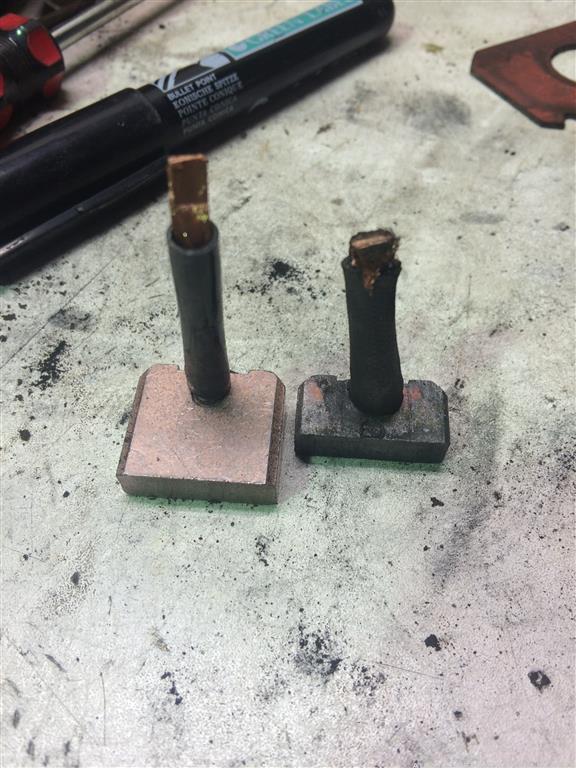
    Gently clean between the commutator segments with a small screwdriver or pick to remove the old carbon deposits. There should still be an undercut of the insulator between the segments, but if its really worn the insulator could be at the same level as the copper. If that's the case you need to get them undercut again or the insulator will hold the brushes up and cause arcing.

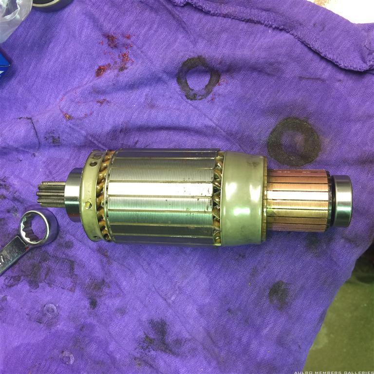
    The ones I've done have still had plenty of undercut left, and with a quick cleanup with emery cloth came up OK:


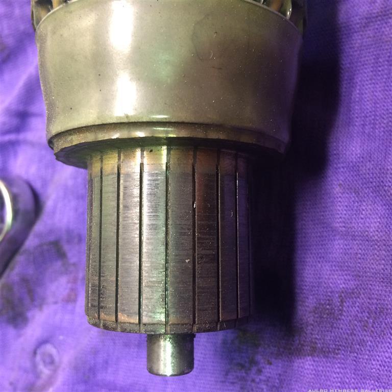
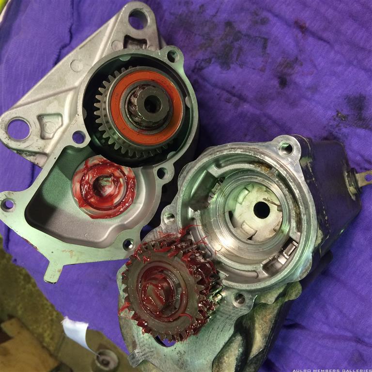
    You can see in that photo that I've replaced the 2 bearings.

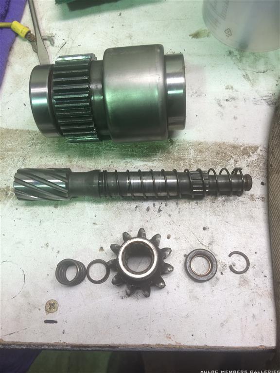
    You can now put the motor parts aside for assembly later.

    Onto the solenoid....

    Remove the 3 screws from the end cap, and remove the cap (taking care not to tear the rubber seal).

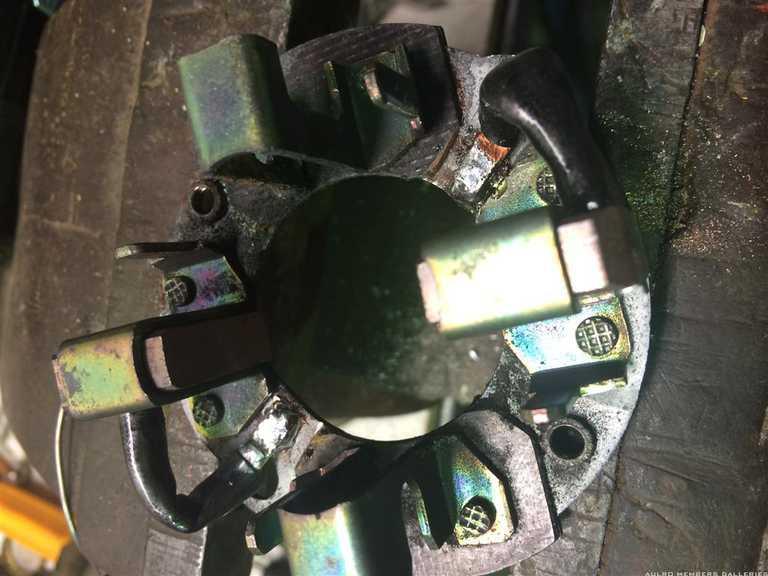
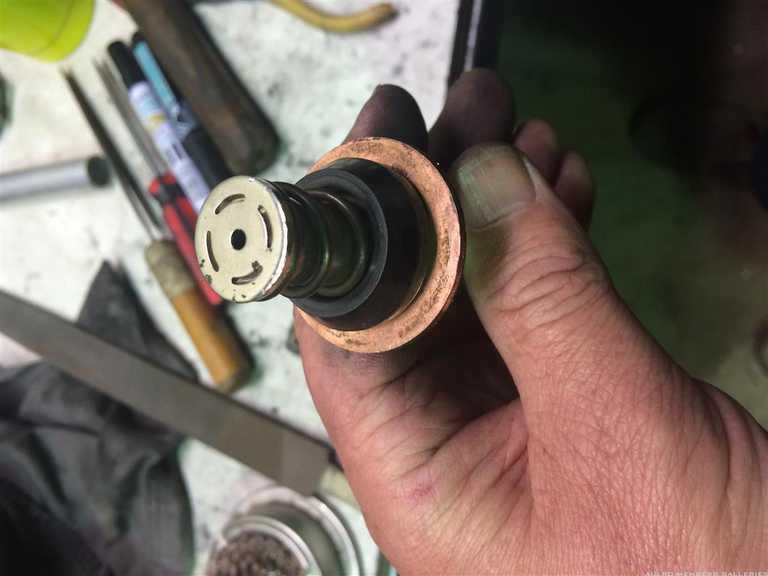
    Remove the solenoid plunger, being careful not to lose the spring and the steel ball that sits below it.

    Here's the plunger:


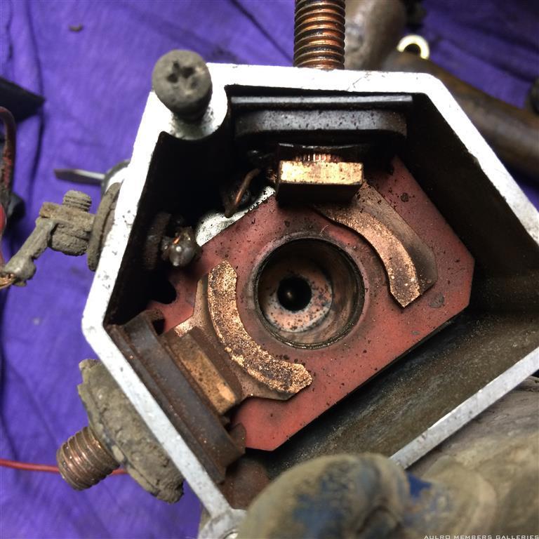
    And inside the housing showing the contacts and (if you look carefully) the steel ball down the hole in the center:


    NOTE: At this point its a good idea to take careful note of how the contacts are assembled, particularly where the wire that runs to the solenoid coil attaches. The lug on the end of that wire is under the head of the upper bolt in the photo. You may have to use a screwdriver or give the bolt a slight tap with a hammer to free it from the contact itself. Needs to be done carefully or you risk damaging the thin lug on the end of the solenoid wire.

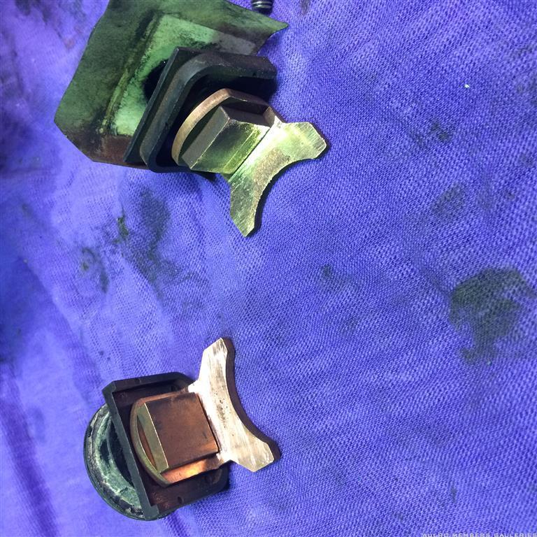
    You can see there's a bit of pitting on the contacts, but not bad and not much wear overall. For this one I just cleaned the contacts up carefully with a file and refitted them. Last time I did one they were worn to around half the original thickness so I sourced some similar ones from Ashdown's and replaced them.

    All cleaned up after removing them.
    If you're paying attention, you'll notice that the cleaned contacts are a different shape. I've come across 2 slightly different solenoid assemblies, with the contact bolts in different positions in the housing. One has an offset contact as above, the other 2 contacts the same (as below).


    More to follow...

    Steve
    1985 County - Isuzu 4bd1 with HX30W turbo, LT95, 255/85-16 KM2's
    1988 120 with rust and potential
    1999 300tdi 130 single cab - "stock as bro"
    2003 D2a Td5 - the boss's daily drive

  3. #3
    Join Date
    Sep 2008
    Location
    Geelong, VIC
    Posts
    4,442
    Total Downloaded
    0
    Time to split the casing containing the gears and pinion throwout mechanism (happy to have my terminology corrected).

    Remove the 2 screws from the flywheel side of the housing, and split it.
    Here's a cleaned up and ready go back together photo but you get the idea:


    The pinion mechanism has 2 bearings (already replaced here), and can easily be disassembled into the following parts for cleaning and greasing/reassembly.
    On the bottom right of the photo is a small malleable steel ring (like a circlip but not hard and springy) that needs to be removed so it comes apart:


    Inside the upper part which has the bearings on it is a roller clutch which I didn't disassemble. Call me a chicken but it was working fine, felt smooth and I decided I didn't need to risk pulling it apart.

    Steve
    1985 County - Isuzu 4bd1 with HX30W turbo, LT95, 255/85-16 KM2's
    1988 120 with rust and potential
    1999 300tdi 130 single cab - "stock as bro"
    2003 D2a Td5 - the boss's daily drive

  4. #4
    Join Date
    Sep 2008
    Location
    Geelong, VIC
    Posts
    4,442
    Total Downloaded
    0

    Putting it back together

    Once you've cleaned and lubed the pinion assembly and reassembled it and put the steel ring back in place you're ready to assembly the major bits back together.

    Its pretty much just the reverse of taking it apart, but here are a couple of tips:

    1. When assembling the gear section, be aware that some may have had a gasket between the 2 halves and an extra shim behind the intermediate gear to allow for the extra thickness. If you're tossing the gasket you'll need to leave out the shim. Whichever way you go make sure the gears still turn freely while you're tightening the 2 screws in the housing (and after you've finished).

    2. Don't forget the ball and spring at the bottom of the solenoid plunger

    3. Long nose pliers on the center of the brush springs allow you to twist them to the right position to push onto the holder.

    4. Getting the commutator back into the brush housing can be tricky. Get creative, but not frustrated
    Sometimes getting 15 fingers in there at the same time you get lucky and can hold the brushes out - sometimes not.
    I've also had success with using a largish socket to hold the brushes back while I insert the commutator.
    Hopefully some starter rebuilding guru has a trick to share will all of us.

    4. If you've got all keen painting it and making it pretty, don't forget that the ground path for the motor is through the brush holder, cover, field housing, gear housing and finally to the flywheel housing.
    Make sure you've got good clean metal to metal contact between:
    - brush holder and cover (where the 2 small screws go through)
    - brush cover and main field winding housing (around the thin edge of the brush cover)
    - field winding housing to gear housing

    Also if you've painted, make sure you clean the paint off inside the brush cover where the bearing seats or you'll have trouble getting it all together.

    O-rings under the long motor bolts are 6x2mm

    Bearings are as follows (one each of the smaller ones, and two of the large ones):


    Steve
    1985 County - Isuzu 4bd1 with HX30W turbo, LT95, 255/85-16 KM2's
    1988 120 with rust and potential
    1999 300tdi 130 single cab - "stock as bro"
    2003 D2a Td5 - the boss's daily drive

  5. #5
    Join Date
    Feb 2014
    Location
    Sydney
    Posts
    1,073
    Total Downloaded
    0
    Excellent write up Steve
    Thanks for the effort
    Regards
    PhilB

    Sent from my MID-744 using AULRO mobile app
    Phil B

    Custodian of:
    1974 S3 swb wagon (sold)
    1978 S3 swb canvas
    48 749 '88 4x4 Perentie
    1985 County with 4BD1T

  6. #6
    Join Date
    Aug 2006
    Location
    Melbourn(ish)
    Posts
    26,495
    Total Downloaded
    0
    the brushes can be held back with plastic cut from a coke bottle wound into a spiral and then forced to expand once you get the brushes started over the comutator.

    you can also use dental floss to pull them back tie a figure 8 on the bite with abou 6 inches of floss on one side of the knot and 10-12 on the other.

    loop the longer section of floss around the brush, feed it through the loop and then secure it. when its time to remove it unsecure the long side and pull the short side. if you got it right the whole lot of floss comes out and you're good to go. Have a practice run first.
    Dave

    "In a Landrover the other vehicle is your crumple zone."

    For spelling call Rogets, for mechanicing call me.

    Fozzy, 2.25D SIII Ex DCA Ute
    Tdi autoManual d1 (gave it to the Mupion)
    Archaeoptersix 1990 6x6 dual cab(This things staying)


    If you've benefited from one or more of my posts please remember, your taxes paid for my skill sets, I'm just trying to make sure you get your monies worth.
    If you think you're in front on the deal, pay it forwards.

Bookmarks

Bookmarks

Posting Permissions

  • You may not post new threads
  • You may not post replies
  • You may not post attachments
  • You may not edit your posts
  •  
Search AULRO.com ONLY!
Search All the Web!