
 The MOD Father
This tutorial kindly supplied by Paul.
"Defender200Tdi"
I've been a bit busy over the last couple of weekends, finally having taken the plunge and splashed out on a set of Maxidrive lockers front and rear, complete with Maxidrive axles, drive members, and an upgrade to AEU2522 CVs too
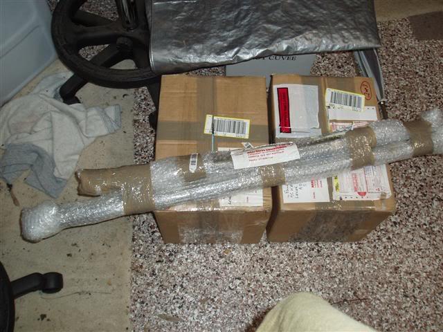
The eagerly awaited packages:
The thing I really liked about the Maxidrive kits is that they were absolutely complete kits. Everything is included, gaskets, mounting screws, zip ties. The vacuum lines were even ready assembled inside lengths of split plastic tube, with the ends already fitted up with olives and the wires already fitted with terminals.
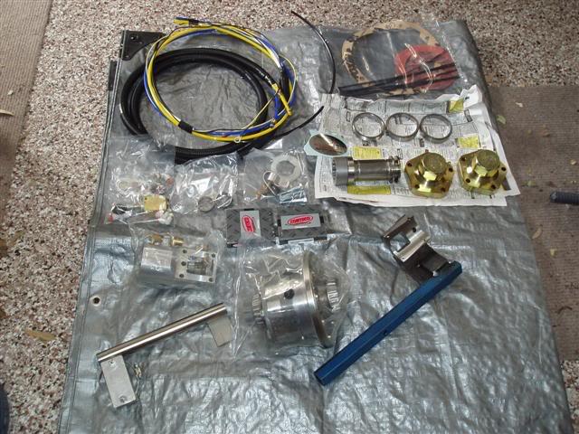
The kit for the Rover front:
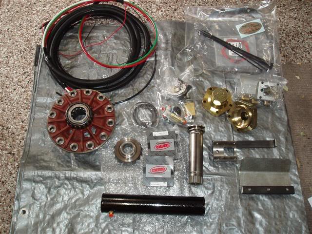
The kit for the Salisbury rear. Note that this kit includes the vacuum tank:
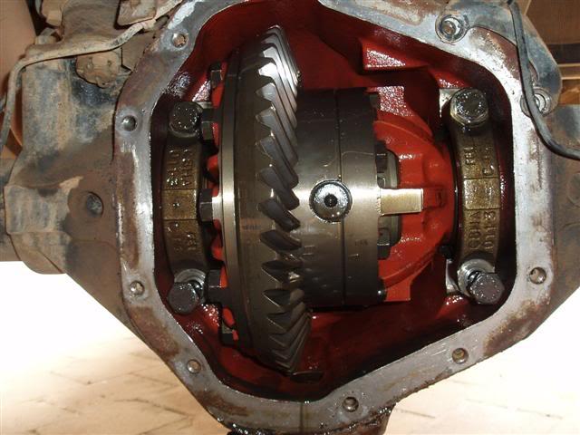
First step in the installation was to remove the Salisbury centre, so it could be pulled down and one hemisphere and one side gear sent off to Mal for Machining.
The Salisbury before dismantling:
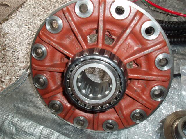
After just 6 days, the hemisphere and side gear had travelled up to Qld for Mal to do his bit, and returned to me. This is the work done on the hemisphere, you can see the splines for the locking dog to engage with, have miraculously appeared:
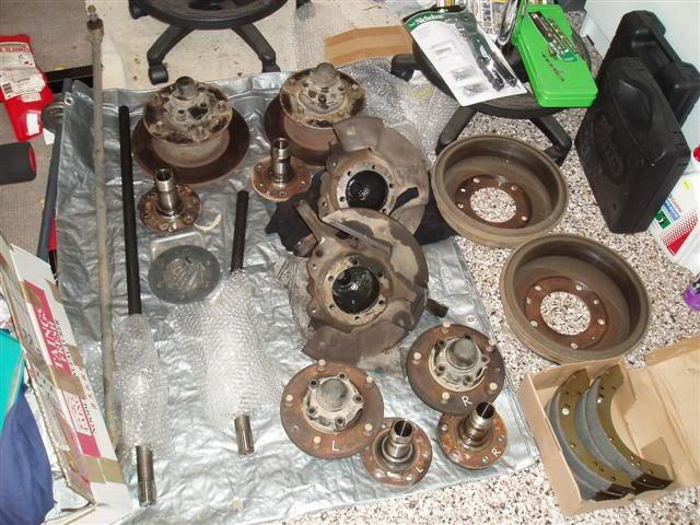
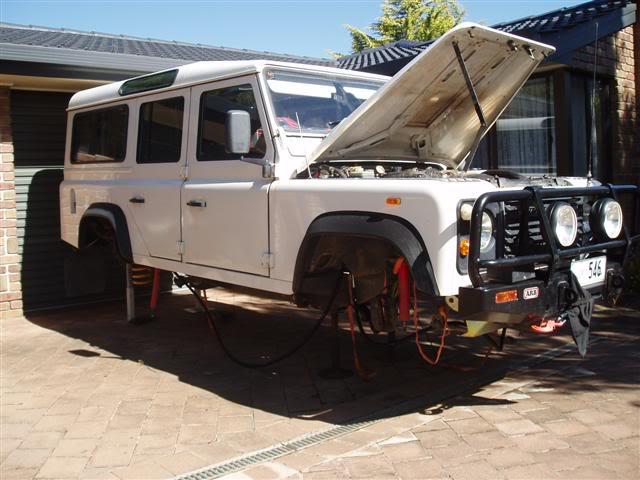
In the meantime, the rest of the axle was removed, likewise for the front. My garage floor very quickly filled up with bits of Defender:
The poor old girl looks a bit sad like this [IMG]file:///C:/DOCUME%7E1/US/LOCALS%7E1/Temp/msohtml1/01/clip_image001.gif[/IMG]
The next step was to cut a hole in each axle casing and weld on the mounting block for the vacuum actuators. This has to be done carefully because it's very easy to turn an almost straight axle into a banana. I say almost straight because Mal reckons the majority of Salisbury tubes are slightly bent right from the factory. [IMG]file:///C:/DOCUME%7E1/US/LOCALS%7E1/Temp/msohtml1/01/clip_image002.gif[/IMG]In most cases this doesn't matter much, but with the Maxidrive lockers any warping can cause the locking dog difficulty in engaging.
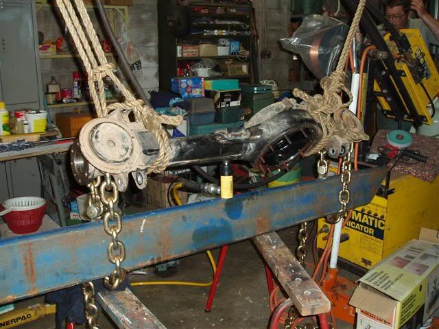
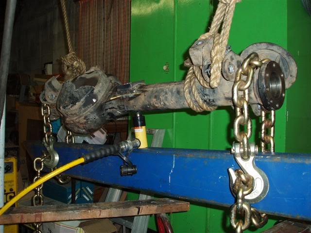
To weld on the tubes correctly they need to be pre-stressed with about 2 tonnes of pressure right opposite the weld point. The best way of achieving this is to use an hydraulic jack between the axle and a strong beam, with the axle chained down at each end. In my case the brother-in-law came to the rescue with the loan of his work's hydraulic porta power. This was a flash one with a pressure readout too, so I could be certain of what force I was pumping in. Here's the front axle rigged up with the porta power straining against a handy length of rhs. Do ya reckon the chains were big enough [IMG]file:///C:/DOCUME%7E1/US/LOCALS%7E1/Temp/msohtml1/01/clip_image003.gif[/IMG]
[IMG]file:///C:/DOCUME%7E1/US/LOCALS%7E1/Temp/msohtml1/01/clip_image004.gif[/IMG]
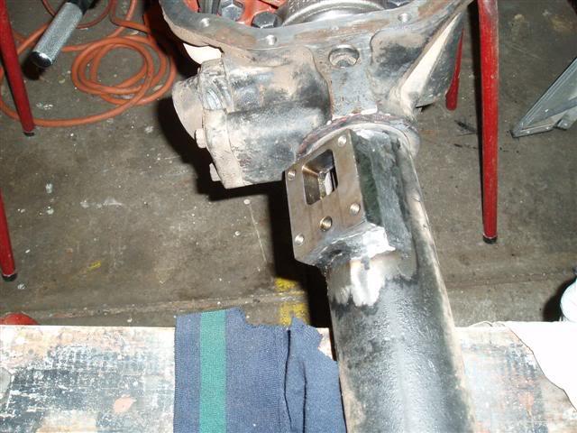
A close up of the freshly welded mounting block on the rear:
Mal includes a jig in the kit to ensure you cut the hole and weld the block in exactly the right place. The best way to cut the hole was to use a carbide die grinder.
It all went quite smoothly for the Salisbury really. Everything went back in easily (with the help of a home made axle spreader), and the backlash came out extremely good, right on the very minimum of specs. The axle casing didn't warp during welding, and I was beginning to wonder when something was going to jump up and bite me on the a#se. [IMG]file:///C:/DOCUME%7E1/US/LOCALS%7E1/Temp/msohtml1/01/clip_image005.gif[/IMG]
Finally the diff was fitted up with the actuator:
[img]http://i2.photobucket.com/albums/y20...20025Small.jpg[/img]
Directly under the actuator in this photo you can see where the mounting for the stone guard is also welded to the casing:
[img]http://i2.photobucket.com/albums/y20...20026Small.jpg[/img]
Next comes the grunting part. Taking the rear axle out was relatively easy because I'd already removed the diff centre to get the hemisphere out to send to Mal. That meant it was a lot lighter than when the fully assembled axle was to be put back in. For a wimpy accountant type like me, those things are a bit of a struggle on your own. [IMG]file:///C:/DOCUME%7E1/US/LOCALS%7E1/Temp/msohtml1/01/clip_image006.gif[/IMG]I got there in the end, and then set about fitting the axles and new brake shoes.
The Maxidrive axles do cause a slight inconvenience when fitting because the locking dog moves on a splined section of the axle, and this section is too large in diameter to fit inside the stub axle. This means that the axle must be fitted before the stub axle. Also, Maxidrive drive members are a tight fit on Maxidrive axles. I mean, knock on with a mallet tight. You must therefore fit the long side axle first, the fit the stub axle and build up the rest of the hub. When you have knocked the drive member on as far as you can and bolted it up, you need to use a long rod from the short side to knock the long axle the rest of the way through the drive member. You can then build up the short side, by knocking the drive member on first. The short axle doesn't have any extra splines, so it fits through the stub axle as normal. Not surprisingly, no shims were needed before the circlips on either side, Mal's tolerances are better than that. [IMG]file:///C:/DOCUME%7E1/US/LOCALS%7E1/Temp/msohtml1/01/clip_image007.gif[/IMG]
The rear axles showing the extra splined area for the locking dog:
[img]http://i2.photobucket.com/albums/y20...40016Small.jpg[/img]
The completed rear fitted up:
[img]http://i2.photobucket.com/albums/y20...90031Small.jpg[/img]
[img]http://i2.photobucket.com/albums/y20...90032Small.jpg[/img]
This one shows the stone guard in place:
[img]http://i2.photobucket.com/albums/y20...90030Small.jpg[/img]
That's about it for the rear really, the rest of the installation happened at the same time as the front Maxidrive.
Here we go for the front (Rover type) axle. First step once again to remove the axle. This wasn’t a difficult thing since the Rover axle weighs bugger all compared to a Salisbury, especially once the swivel housings have been taken off.
After setting up the housing to pre-stress it, it was just a matter of taking to it with the die grinder to cut the hole, and welding on the mounting black for the vacuum actuator. Once again, Mal supplies a jig to set up the mounting block in exactly the right place. Even I couldn’t stuff that up.
Here’s the block after welding. No comments on the cocky poo please.
[img]http://i2.photobucket.com/albums/y20...80089Small.jpg[/img]
The front was pretty easy to build up because most of it gets thrown out. Only the crown wheel remains, which is transferred on to the new Maxidrive centre. The new centre comes complete with the bearings already fitted. Very nice of Mal, don’t you think?
The most interesting part of this is the change to the locking tab thingy that mounts on the bearing caps.
In this photo you can see the locking thingy on the top of the bearing cap. The other side was originally the same:
[img]http://i2.photobucket.com/albums/y20...80092Small.jpg[/img]
The side where the locking dog engages gets a bit of surgery. Basically, the mount for the locking thing gets a date with Mr Hacksaw and Mr File, then drilled and tapped to take a bolt holding a small bit of angle in place. You then mark up the angle and cut it out to make a new locking tab:
[img]http://i2.photobucket.com/albums/y20...80091Small.jpg[/img]
After grinding and starting to coat with some cold galv stuff, I was ready to fit up the actuator:
[img]http://i2.photobucket.com/albums/y20...80093Small.jpg[/img]
[img]http://i2.photobucket.com/albums/y20...80094Small.jpg[/img]
Then it was just a matter of sticking it all back together.
[img]http://i2.photobucket.com/albums/y20...90029Small.jpg[/img]
[img]http://i2.photobucket.com/albums/y20...90028Small.jpg[/img]
Even though the actuator is on the front of the axle, it’s right at the top and protected by the steering guard and the panhard rod. If I hit anything high enough to bother the actuator, I think it’ll be the least of my worries:
[img]http://i2.photobucket.com/albums/y20...90027Small.jpg[/img]
Since my 200tdi has the old style swivel housing, changing to the AEU2522 CVs was straight forward. I already have the bronze bush in the stub axle, and the early CVs are the same size and therefore a simple fit. The Maxi axles are also straightforward, although the tight fit of the Maxi drive members onto the CV stubs is a bit of a pain. No doubt they’ll loosen up a bit with use.
[img]http://i2.photobucket.com/albums/y20...90033Small.jpg[/img]
The rest of the installation revolves around fitting the switches and vacuum lines and tank.
Maxidrive lockers use vacuum lines to both engage and disengage the locking dog. They also include a third line which is the breather. The factory breather banjo fitting is removed for both front and rear, and the hole is filled with a plug.
Vacuum for the Maxidrives is supplied by the vacuum pump simply by cutting into the line to the brake booster:
[img]http://i2.photobucket.com/albums/y20...20019Small.jpg[/img]
A non-return valve is fitted into the line that feeds the two switches (valves actually) and the small (supplied) tank. Usually the tank is mounted under the blank plate on the RH wing, but mine is crammed full of manifold and pressure switch etc for the onboard air system. The best spot I could find was under the brake booster, mounted to the inner guard. Once again, all mounting hardware, brackets etc are included in the kit:
[img]http://i2.photobucket.com/albums/y20...20020Small.jpg[/img]
The Maxidrive system is all pneumatic and uses pneumatic switching too. The control valves (on/off switches) look like this:
[img]http://i2.photobucket.com/albums/y20...20018Small.jpg[/img]
The valves could be mounted in any protected space (but they do draw in air, so need to be dust/water free). I chose to go along with Mal’s suggestion and mounted them here:
[img]http://i2.photobucket.com/albums/y20...90035Small.jpg[/img]
The warning lights are also mounted up in the place suggested in the instructions, but they could be just about put anywhere that takes your fancy:
[img]http://i2.photobucket.com/albums/y20...90036Small.jpg[/img]
The only electrics involved are for the warning lights. Unlike the ARB lockers, the warning lights show whether the Maxidrives are engaged, much like the light for the LT230 centre diff lock. The ARB lights just show when the switch is on.
Well, that’s it. A couple of weekends work and a few dollars out of the savings account. [IMG]file:///C:/DOCUME%7E1/US/LOCALS%7E1/Temp/msohtml1/01/clip_image008.gif[/IMG]Overall I couldn’t fault the Maxidrive kits. As I said before, everything is included and the instructions and photos supplied are first class. They’re not as easy to fit as the ARBs because you have to weld on the mounting blocks, but they have a reputation for being much stronger and absolutely trouble free. They are also better value when you take the cost of the axles and everything else into account.
This info supplied by
Paul
"Defender200Tdi"
Last edited by Pedro_The_Swift; 20th May 2007 at 12:38 PM.
"How long since you've visited The Good Oil?"
'93 V8 Rossi
'97 to '07. sold.
'01 V8 D2
'06 to 10. written off.
'03 4.6 V8 HSE D2a with Tornado ECM
'10 to '21
'16.5 RRS SDV8
'21 to Infinity and Beyond!
1988 Isuzu Bus. V10 15L NA Diesel
Home is where you park it..
[IMG][/IMG]
 Posting Permissions
| Search AULRO.com ONLY! |
Search All the Web! |
|---|
|
|
|


 Reply With Quote
Bookmarks