


 Reply With Quote
Hey Angus! Thanks! Good to hear from you mate, it's been ages! I'm going to have to keep pushing and pushing to get this job done... there is certainly a lot of work to do.Originally Posted by McDisco

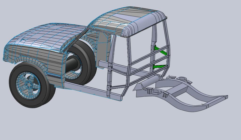
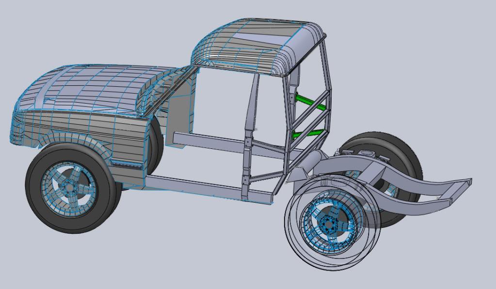
Right as for an update.
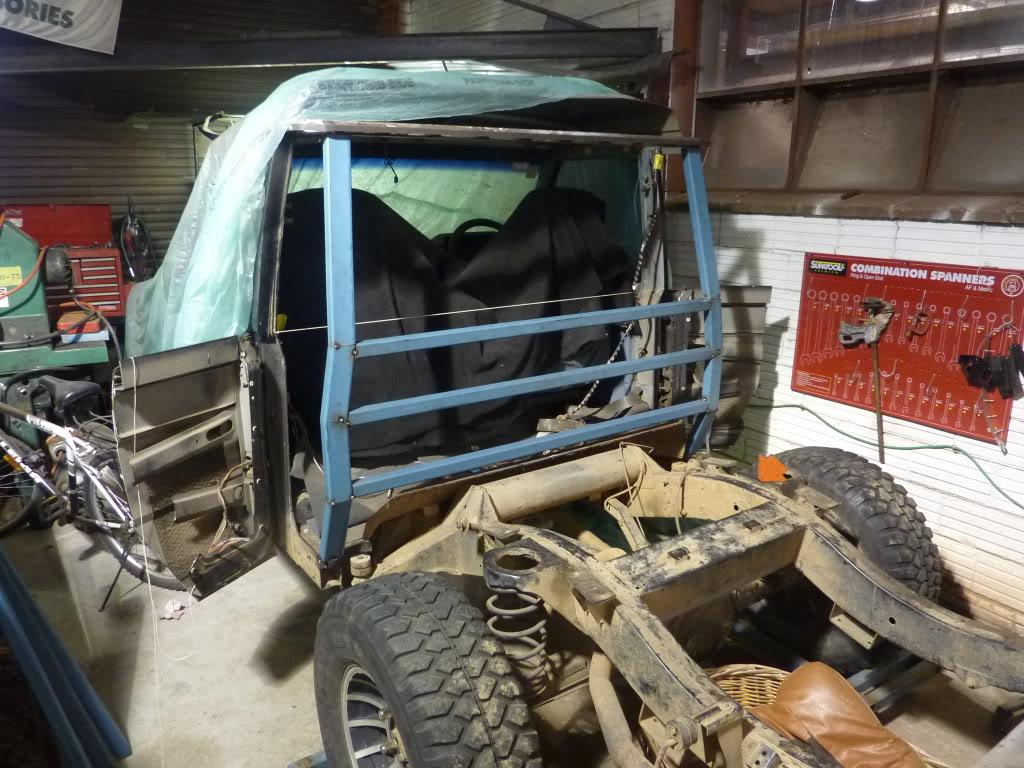
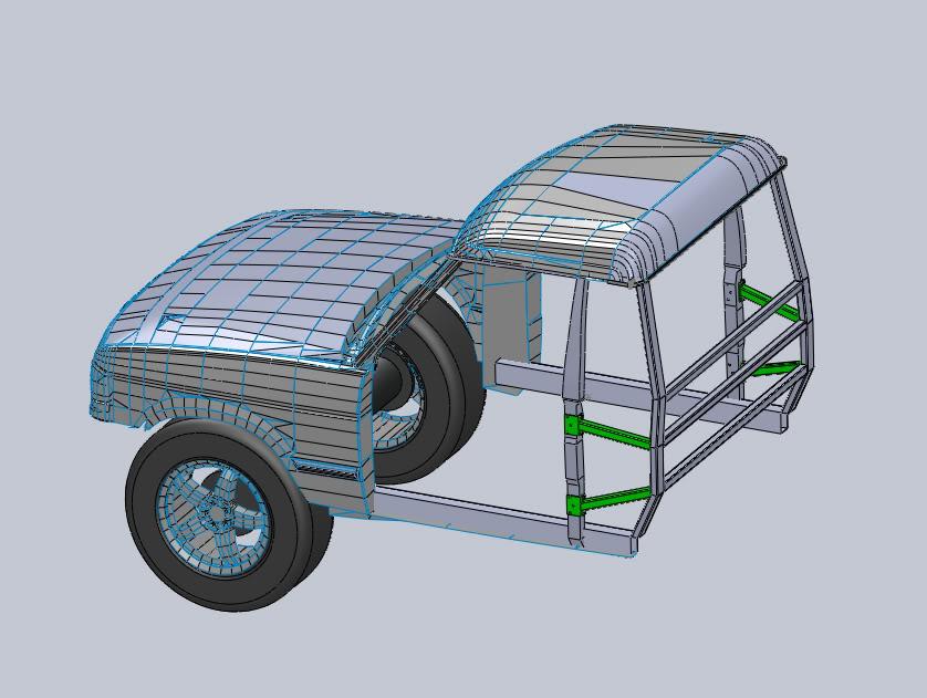
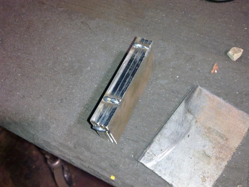
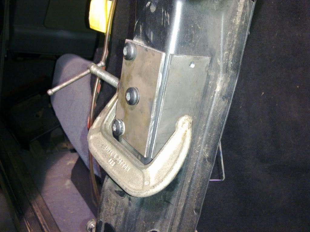
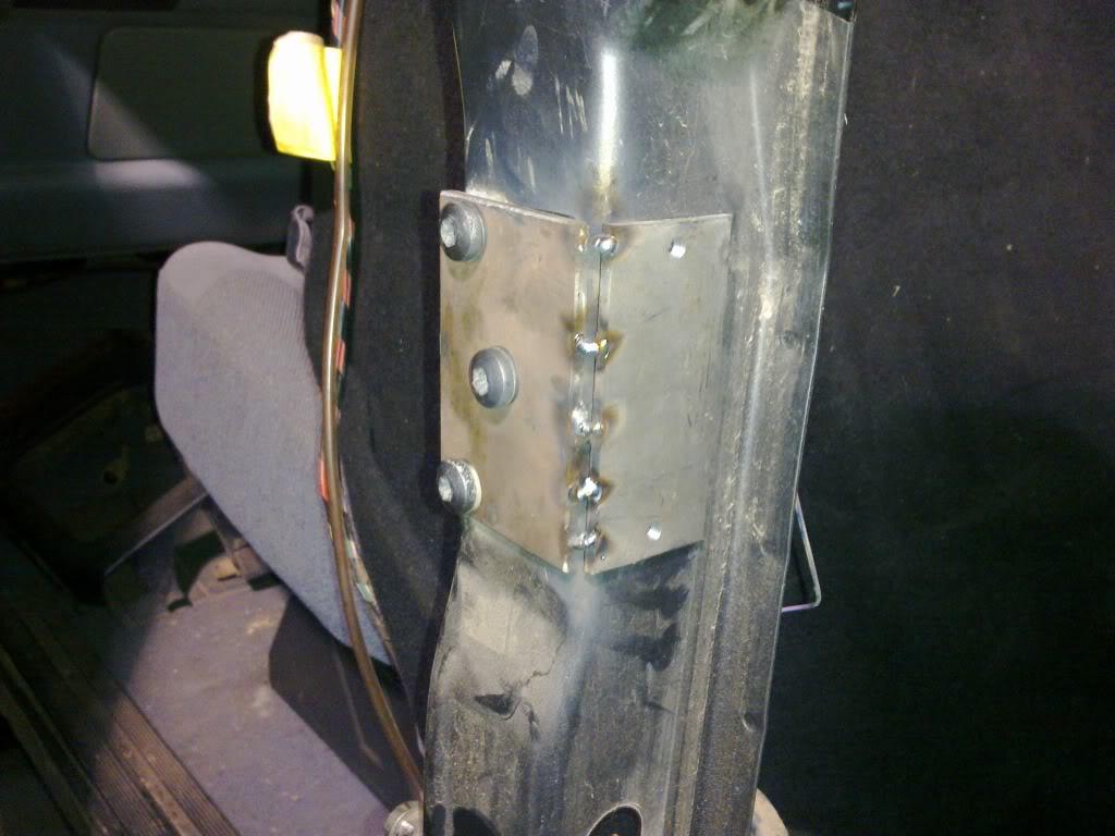
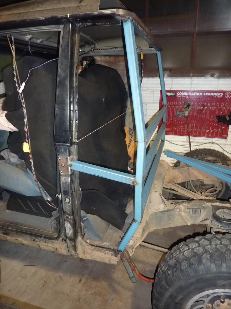
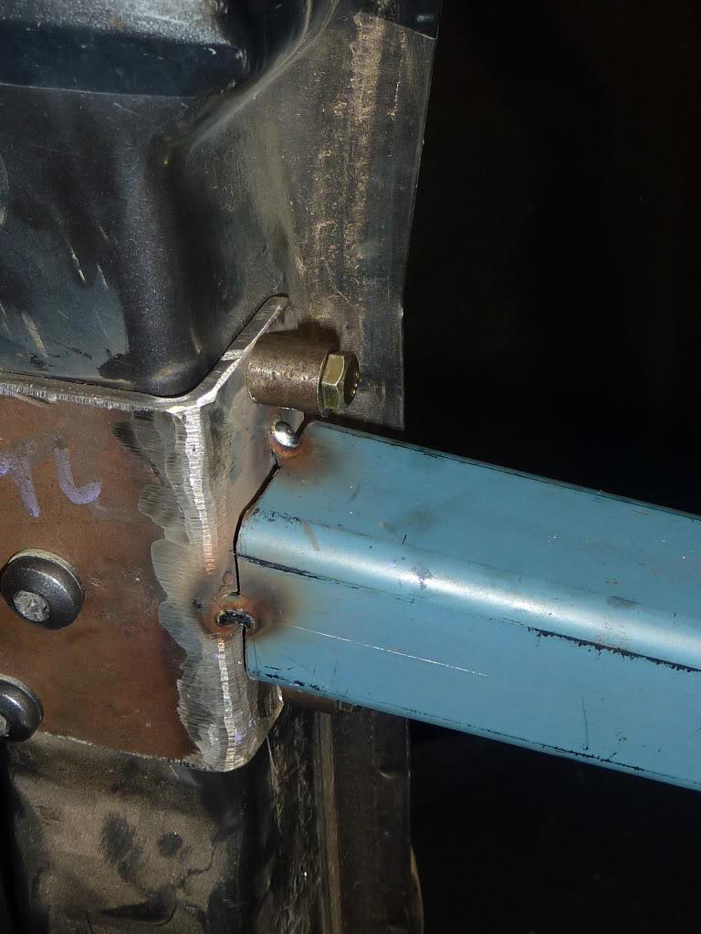
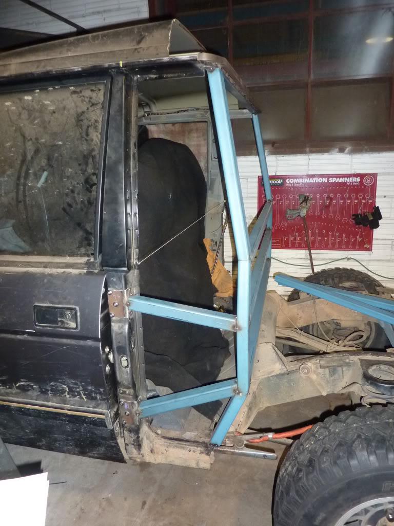
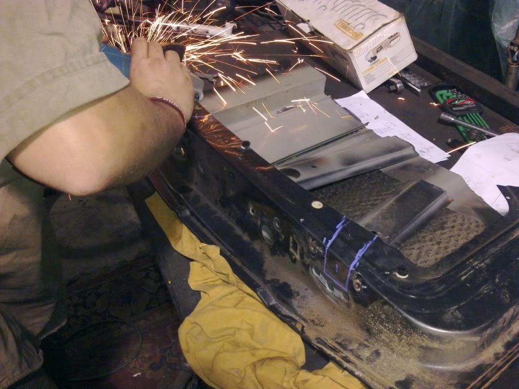
I went in to the workshop to cut and tack weld in the upper horizontal brace for the wall.
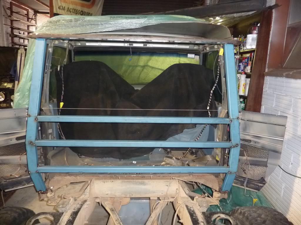
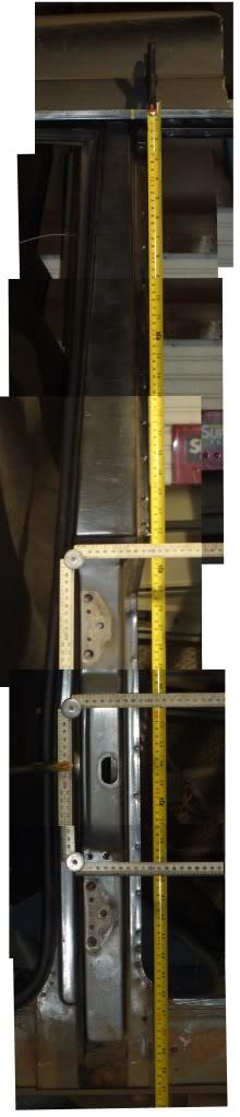
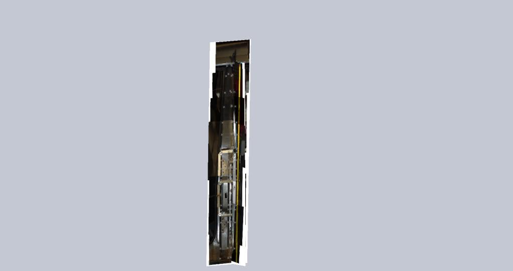
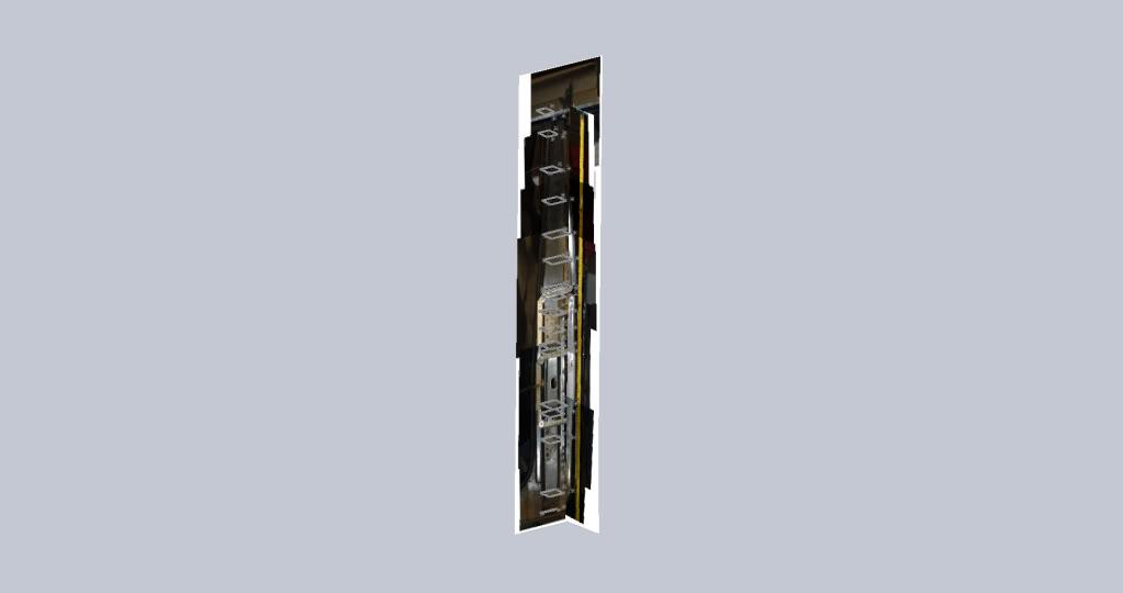
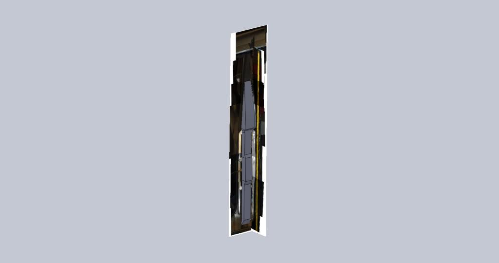
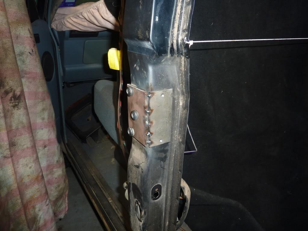
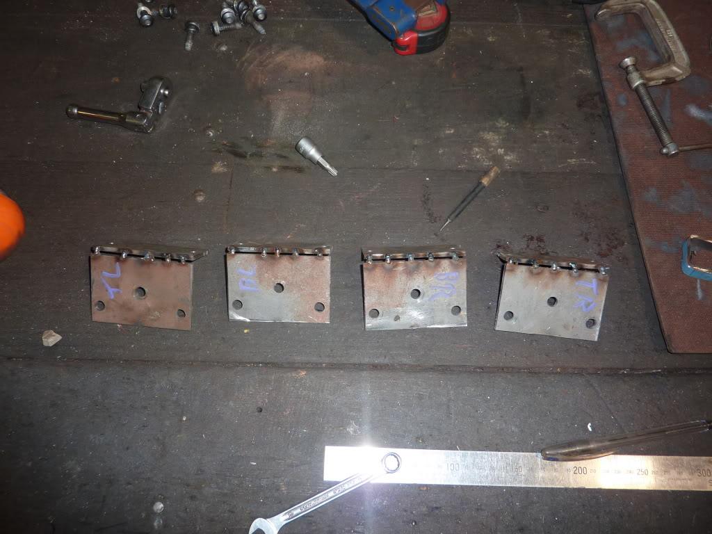
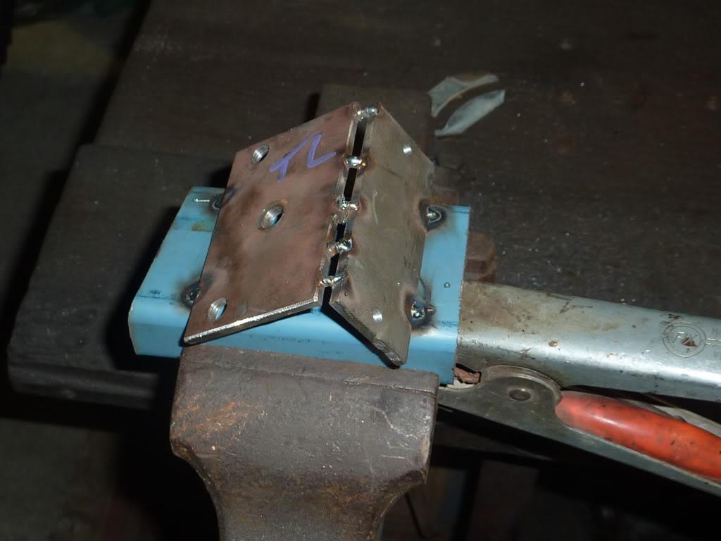
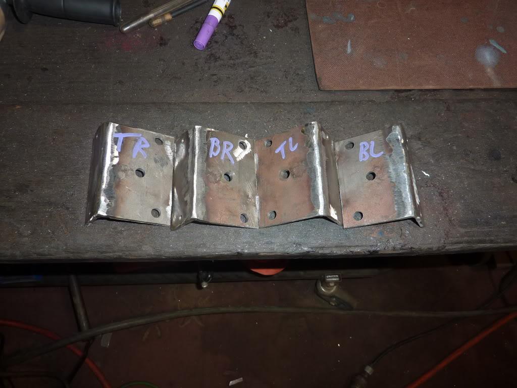
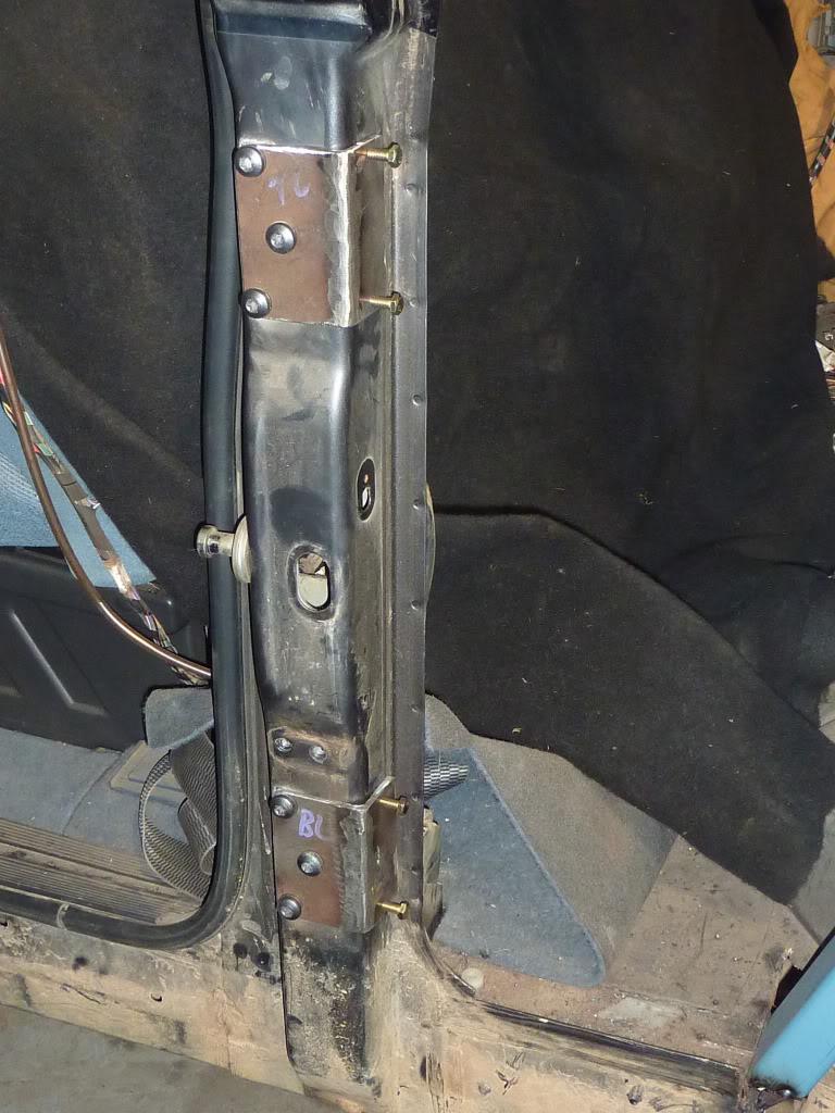
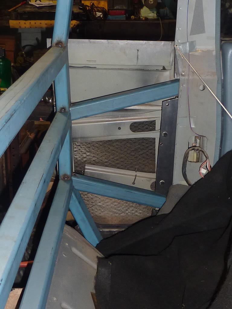
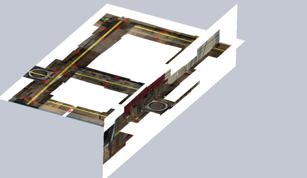
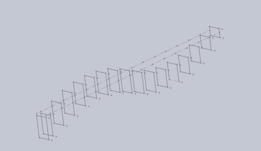
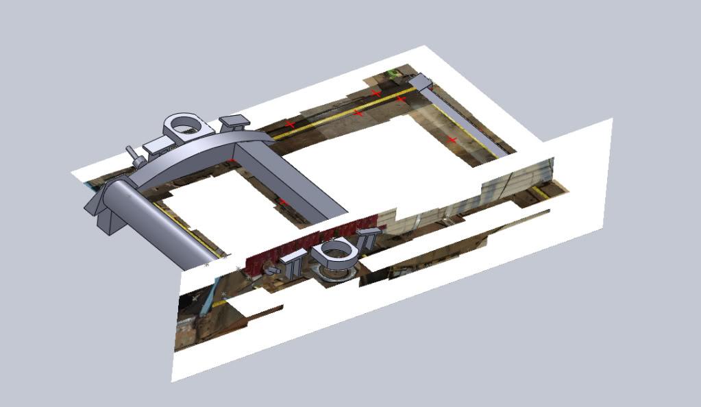
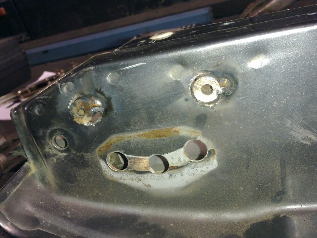
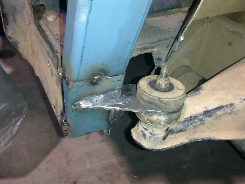
So the rear part of the frame is done (in terms of cutting and tack welding anyway). Now I need to get the design of the side braces finalised, but before I can do that I need to get a little more info for my model. So the rest of the time was spent taking photos of the side braces to be able to mosaic them in to a side and rear view.
Side view:
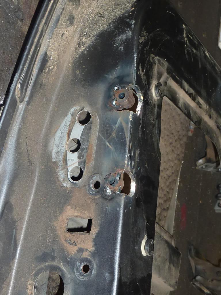
Rear View:
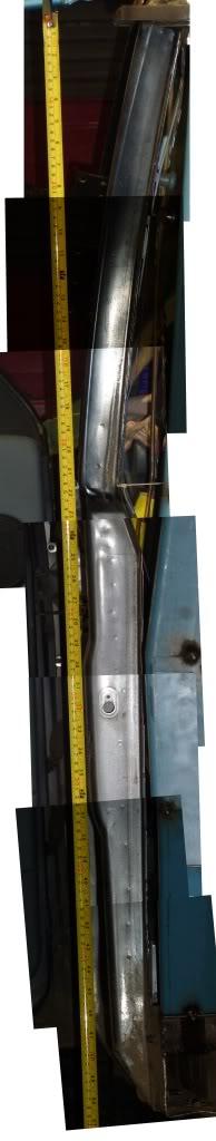
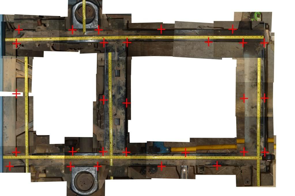
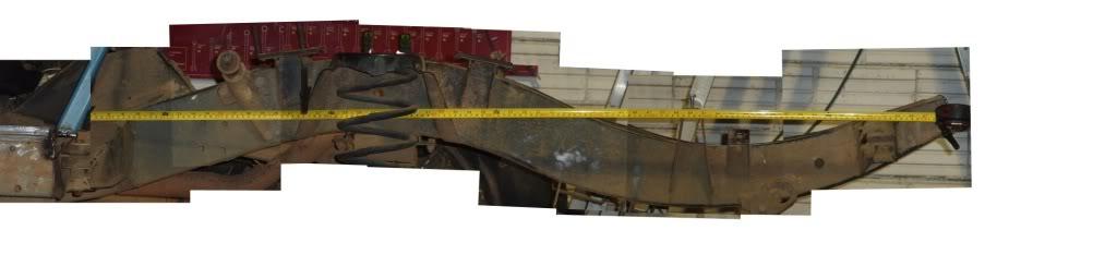
You may be wondering why I did this in multiple photos. The reason for that is that the lens of the camera bends and image towards the edges, so to reduce this effect you need to use smaller pieces when you want to use a photo as a geometry reference.
While I was at it, I also took a bunch of top and side photos of the exposed portion of the chassis so that it can be modelled as well... Although I haven't had time to go and align all the photos and join them together (it takes ages)
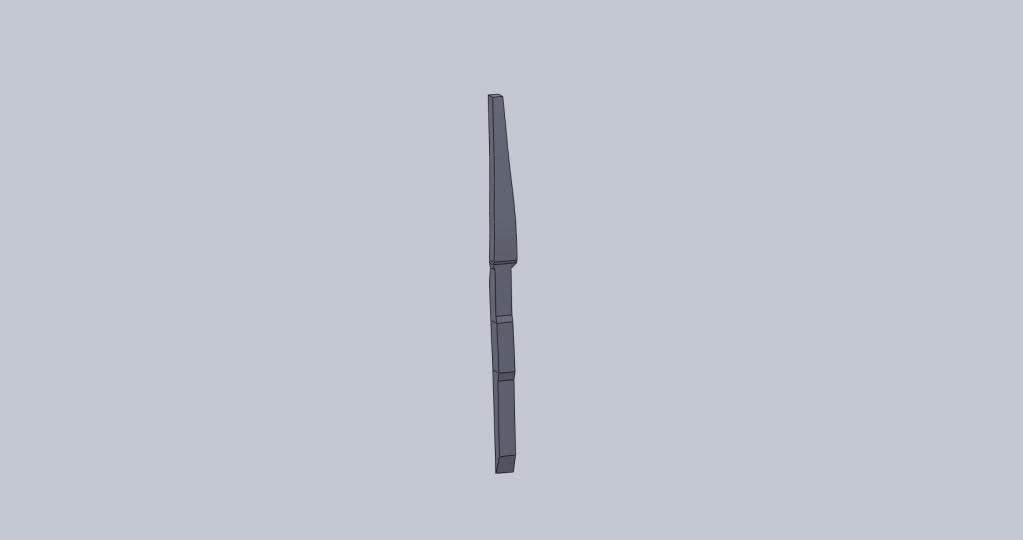
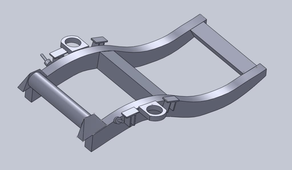
Hopefully over the course of next week I will produce the model of the B pillar and then finalize the design of the side braces to fabricate them up next weekend.
That's it for now.


Bookmarks