Your recommendations are also flawed...
Add a Radius or slot and the pin will point load, bringing the same issue.
A 90 degree bend will add a stress to the steel and increase torsional loading and would need to be braced.
Then during a recovery above or below the horizontal plane the same issues will occur (loading the pin)
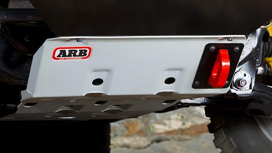
Unless a design incorporates a
self aligning recovery point at some stage the recovery will be out of alignment.
A 3.2t shackle is highly
unlikely to fail in a vertical recovery point, when used with a bridle on any recovery.. The strap attached is only rated to 8,000kg (pin failure occurs at approximately 22t (22,000kg).
The strength of the chassis is far below this...
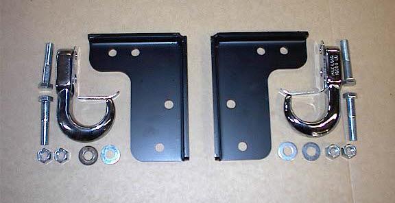
Here is a reasonable design that can handle offset.
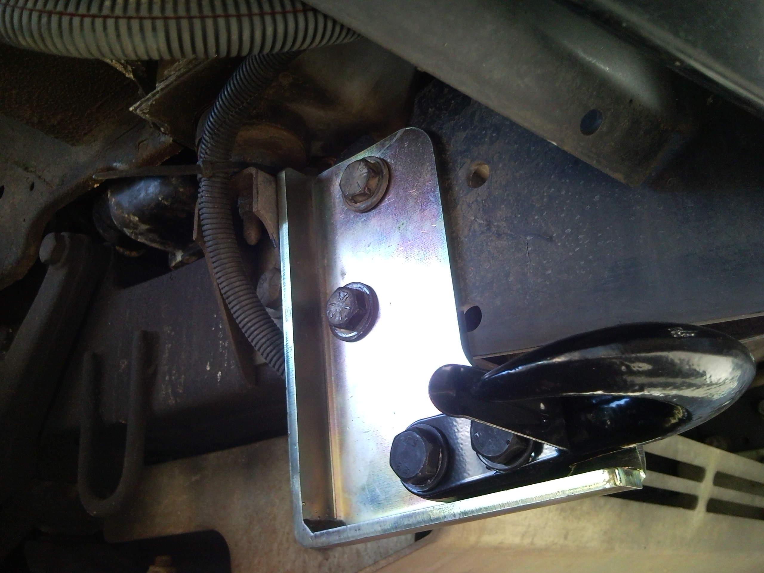
or there is this custom made example (would not be certified rated) and I would question the single point mounting (but a modification could be an option)

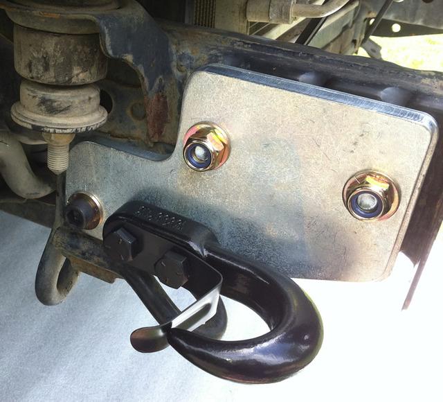
Or an adaptation of this


Originally Posted by Islandnomad

")

Bookmarks