Hi Jon
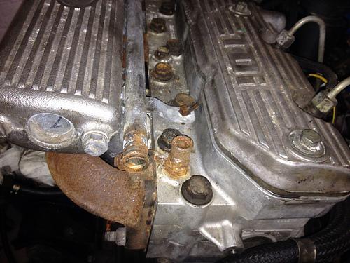
I don't like the idea of interfering with the top hose, too much movement there for my liking. Instead I'd investigate the unused bung just forward of the rear heater hose fitting in the top of the head.
Years ago when I was just as silly and without any wisdom at all, I fitted a gauge into the instrument cluster by removing the segment that contain the light and fitted a gauge from a Rover 75 car instrument cluster. Make a electronic voltage regular for your instruments as there is a lot less, to no electrical noise generated and that does allow everyone else in the convoy to be able to enjoy their radios.

Before you install your engine, how have you gone about determining the correct position where the engine sits, will the top of the diff housing clear the sump when on hitting a bump with the RHS front wheel?
I see that you are fitting this engine into a 86", pity is it wasn't a S1 88" as then that diff clearance issue wouldn't occur.
If you can find a Diesel series 1 to have a look at, that would be good to copy things like the layout of fuel lines, the wiring loom, etc.
With the clutch bell housing, I have been looking at fitting a hydraulic series 3 clutch and housing arrangement, The housing would need to be fitted to the either late series 2a six cylinder gearbox because of the larger layshaft bearing size or keep a series 3 gearbox, this would also require the fitting of pendulum pedal set from the series 3 as well. This is not a bad idea as it simplifies the fitting of a vacuum booster for the brakes.
.


 Reply With Quote
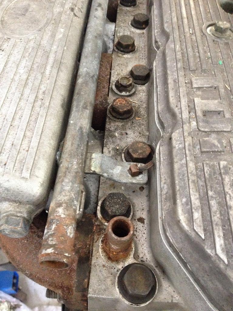
")

Bookmarks