Page 2 of 3 FirstFirst 123 LastLast
Results 11 to 20 of 23

Thread: Fuel problems

  1. #11
    Join Date
    Aug 2006
    Location
    Melbourn(ish)
    Posts
    26,497
    Total Downloaded
    0
    dont forget that if you have a blocked emulsion tube air feed port you will draw excessive fuel as the carby will only be drawing neat fuel and not a blend of air and fuel.


    easy to spot, the fuel coming out into the throat of the carby when you look down into it (use a mirror in case it backfires at you) wont look like a mist but more like a "wash" of larger droplets.
    Dave

    "In a Landrover the other vehicle is your crumple zone."

    For spelling call Rogets, for mechanicing call me.

    Fozzy, 2.25D SIII Ex DCA Ute
    Tdi autoManual d1 (gave it to the Mupion)
    Archaeoptersix 1990 6x6 dual cab(This things staying)


    If you've benefited from one or more of my posts please remember, your taxes paid for my skill sets, I'm just trying to make sure you get your monies worth.
    If you think you're in front on the deal, pay it forwards.

  2. #12
    Join Date
    Oct 2015
    Location
    Buenos Aires, Argentina
    Posts
    26
    Total Downloaded
    0
    Quote Originally Posted by Busted Syncro View Post
    G'day Paul,

    OK on the choke cable and all working properly.

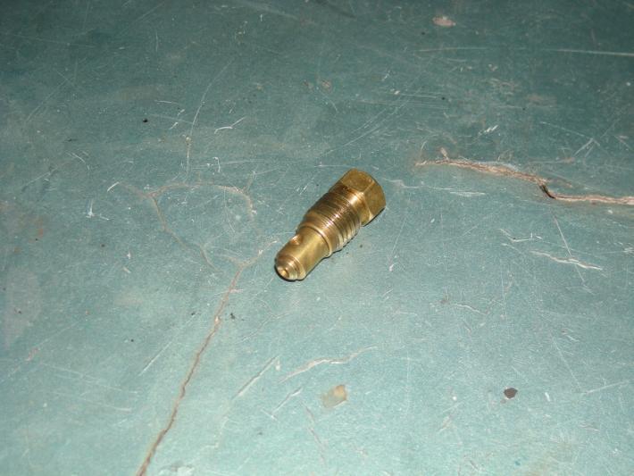
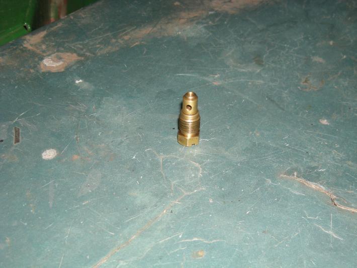
    The Starter and the Accelerator pump jet will only fit in the correct position. However, the accelerator pump non return valve will also fit in the Starter jet position by mistake.

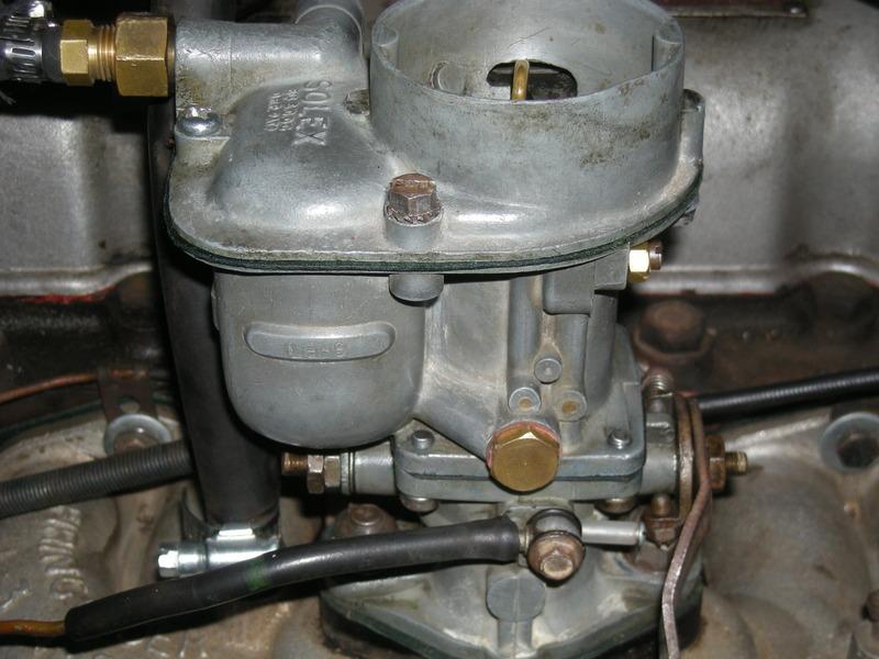
    It concerns me the choke tube does not have a number like 35-40-26 or
    35-40-28 or 35-40-30 on the rounded lip. ( It may have been filed off to improve air flow?)

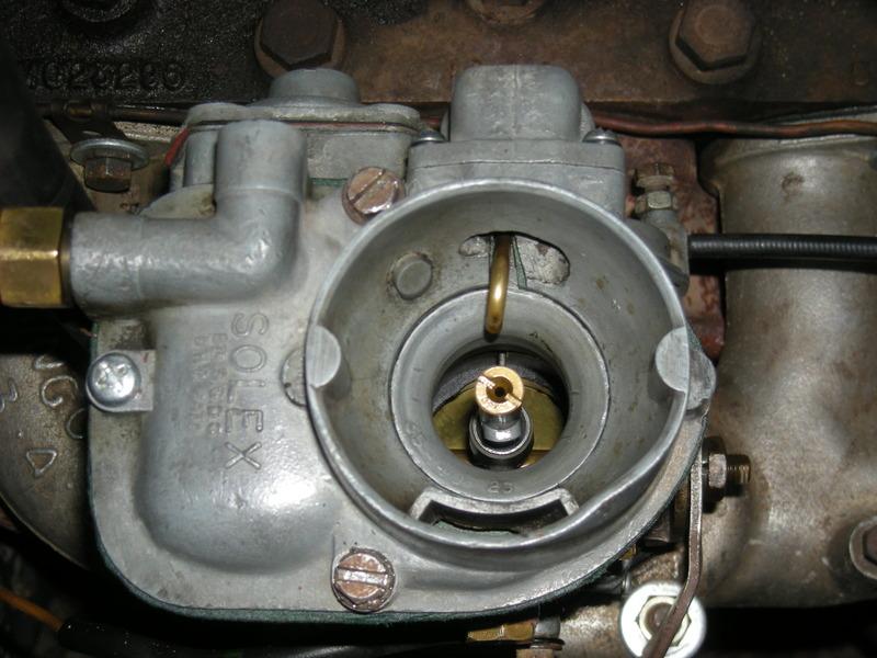
    Can you take a photo looking down the throat of the carburetor for me by lifting off the air cleaner pipe.

    The rounded edge of the choke tube should be at the top of the carburetor.
    You can measure the internal diameter of the choke tube from the round lip end. It will be 26, 28 or 30 mm.

    The pilot jet fuel feed comes from the top of the main jet gallery. Very difficult to clean. Lots of carby cleaner and compressed air needed here. Same problem with the 75mm gallery to the idle fuel screw to clean. There is also a bypass orifice 34mm below the pilot jet in this gallery which maybe blocked.

    Are you still having fun ?????

    Chris
    I will check all this over this weekend, and take more photos
    Many thanks

    of course the fun just begun


    Yes Dave, I saw a lot of fuel on the throat but since I cover the hole for the idle screw everything's all right now

  3. #13
    Join Date
    Oct 2015
    Location
    Buenos Aires, Argentina
    Posts
    26
    Total Downloaded
    0
    OK here are more pics form the carb, it say 35-40-26


  4. #14
    Join Date
    Nov 2014
    Location
    Sydney
    Posts
    210
    Total Downloaded
    0
    G'day Paul,

    Thank you for the excellent photo's.

    Nothing appears wrong and note the modification for the vacuum line and spring on the choke cable.

    However, the pilot jet looks different to the type I use. Can you remove it and take a series of photo's please as this could be one of your problems with the idle circuit.!!

    Cannot read the size of the air correction jet however, should be 185 to start with. The choke tube is fitted the correct way and note it is 26mm.

    Before you can work on the fuel consumption and loss of power at 70Km you need to fix the idle problem.

    There is fuel restriction in the idle fuel circuit somewhere and will cause problems later because at the moment you cannot adjust the idle mixture correctly. The engine can idle at 600 rpm OK which is a good sign.

    Interesting the full repair kit for the Solex included a new pilot jet. The hole is only 0.6mm diameter and can easily block up with dirty fuel or clog up the fuel galleries in the idle fuel circuit. Plenty of compressed air needed here!!!!!. The range of jet sizes allows you to fine tune the position of the volume control screw adjustment.

    Chris

  5. #15
    Join Date
    Oct 2015
    Location
    Buenos Aires, Argentina
    Posts
    26
    Total Downloaded
    0
    Ok Chris thanks. The air correction is 180 I buyed a 185 so will change this weekend.
    The pilot jet is 55, looks nornal in the photo is overlap with the screw rear (the one is fix the choke tube)

    I will continue clean the galleries with more air compressed this weekend

  6. #16
    Join Date
    Nov 2014
    Location
    Sydney
    Posts
    210
    Total Downloaded
    0
    G'day Paul,

    Ok on the air correction jet. Going from 180 to 185 will lean out the mixture at the high rev range.
    This jet operates effectively from about 2000rpm and above.

    The reason the pilot jet looks different is the thickness of the Hex head. It appears not genuine Solex or a jet from another Solex model and not a 40PA10. The thickness of the genuine hex is 1.82mm. This is to make sure the jet seals on the tip where the 0.55mm hole is and not on the Hex part. There should be a gap of approx. 0.9 mm between the end of the Hex and the casting. Maybe a couple of photos will help identify the jet.

    My thinking is to get your idle circuit back to original specification and work from there to fix the problem if it's still there.

    Some of the aftermarket jet kits don't have the size stamped on them. My concern is what else have they changed in the specifications. I remember in your first post you thought "Maybe the jets in the carburator ara to big."

    With anything aftermarket for Series Landrovers you have to check everything is the same as the original part!!!.

    When I go to swap meets and car part sales I'm on the lookout for genuine Solex to recover the jets and other genuine bits.

    Another thought:: Because the vacuum advance connection to the Solex is not standard maybe the tread size is larger in diameter than the original and has broken into the idle screw port and created another path for air to leak in?. Maybe your plastic tube has sealed this off?.
    The original thread for the tube nut into the vacuum advance port is M6 x 1.00 and hopefully it is still the same.

    Keep up the good work!!!!

    Chris

  7. #17
    Join Date
    Oct 2015
    Location
    Buenos Aires, Argentina
    Posts
    26
    Total Downloaded
    0
    Ok Chris, here is it


  8. #18
    Join Date
    Nov 2014
    Location
    Sydney
    Posts
    210
    Total Downloaded
    0
    G'day Paul,

    Thank you for the photos.

    Looks Solex genuine however, not for a 40PA10. The difference is the thickness of the Hex head and the number of threads. I see 5 on yours and all mine are 7 threads. ( Thread is M8 x 1.00)

    The critical measurement length wise is from the tip to the Hex. All mine are between 17.22mm and 17.16mm which gives a clearance of approx 0.9mm between the hex and the casting when jet seated correctly on the tip.
    Check to make sure yours when fitted has a clearance between the Hex and the casting. That way you know the tip is sealing correctly.

    If it is seating on the Hex and casting your jet supplier should have the correct jet with the thin hex.

    Still having Fun????
    Chris

  9. #19
    Join Date
    Oct 2015
    Location
    Buenos Aires, Argentina
    Posts
    26
    Total Downloaded
    0
    I wasn't with the series this weekend, but my father says it is working, so he put it to work


    Next weekend continue testings

  10. #20
    Join Date
    Nov 2014
    Location
    Sydney
    Posts
    210
    Total Downloaded
    0
    G'day Paul,

    Excellent. That's what the LandRover was made for...

    Let us know what the engine number and the casting number on the cylinder head is please.

    Chris

Page 2 of 3 FirstFirst 123 LastLast

Bookmarks

Bookmarks

Posting Permissions

  • You may not post new threads
  • You may not post replies
  • You may not post attachments
  • You may not edit your posts
  •  
Search AULRO.com ONLY!
Search All the Web!