Results 1 to 9 of 9

Thread: K thermocouple cable length

  1. #1
    Join Date
    Jan 1970
    Location
    VIC
    Posts
    3,536
    Total Downloaded
    0

    K thermocouple cable length

    I have a 6mm VDO thermocouple wired to a VDO pyro via the supplied 5m "compensating cable" (one wire is copper, the other is something else).

    I've just bought an Auber exposed tip thermocouple which is suppled with 1.8m of cable. Obviously it advises not to change the length of the cable, but if put a K-type plug on the end and plug it into the VDO compensating loom will it be accurate?

  2. #2
    Join Date
    May 2007
    Location
    Australia
    Posts
    2,827
    Total Downloaded
    0
    Maybe contact Auber for their advice?

    My understanding is that the cable resistance is critical over the supplied length to ensure accurate reading.

    Someone like "Drivseafe" with an in depth electrical knowledge hopefully will come along soon if Auber cannot help.

    cheers

  3. #3
    slug_burner is offline TopicToaster Gold Subscriber
    Join Date
    Jul 2007
    Location
    Melbourne
    Posts
    4,024
    Total Downloaded
    0
    It is the dissimilar metals that pruduce the temperature sensitive junction. Every junction will produce a voltage proportional to the temperature at the junction. It comes down to what you consider accurate!

  4. #4
    Join Date
    Jan 1970
    Location
    Travelling OZ - Back in SE Qld again at the moment
    Posts
    672
    Total Downloaded
    0
    Quote Originally Posted by B92 8NW View Post
    I have a 6mm VDO thermocouple wired to a VDO pyro via the supplied 5m "compensating cable" (one wire is copper, the other is something else).

    I've just bought an Auber exposed tip thermocouple which is suppled with 1.8m of cable. Obviously it advises not to change the length of the cable, but if put a K-type plug on the end and plug it into the VDO compensating loom will it be accurate?
    As Drivesafe says, dissimilar metal junctions cause errors in thermocouple circuits. You can extend thermocouple cables (up to >100m in industrial situations in the past) using either the same thermocouple alloy wires or compensating extension cable which has the same thermoelectric properties over a limited temperature span.

    Is the VDO cable you're considering the stuff with a redish-brown PVC sheath and red and brown covered wires? If so, it should be an international standard compensating cable for type K.

    Are you planning on attaching the Auber probe to your existing VDO analog gauge? If so, I suggest you ensure the total length of cable from the probe to the gauge terminals is a close as possible to that of the original VDO sensor. Analog gauges such as this are low impedence devices and are calibrated not only to the thermoelectric characteristics of the thermocouple but also to allow for the total resistance of the sensor cable. Electronic thermocouple gauges are high impedence devices and are generally unaffected by cable resistance changes.

    By the way, I wouldn't use the Auber exposed tip T/C in a pre-turbo (upstream) situation. I'd only ever use a fully sheathed T/C pre-turbo.

    Ian
    Ian &
    Leo - SIII 109/GMH3.3
    Daphne I - '97 Disco 300Tdi Manual
    Daphne II - '03 Disco Td5 Auto

  5. #5
    Join Date
    Jan 1970
    Location
    VIC
    Posts
    3,536
    Total Downloaded
    0
    Quote Originally Posted by Leo109 View Post
    As Drivesafe says, dissimilar metal junctions cause errors in thermocouple circuits. You can extend thermocouple cables (up to >100m in industrial situations in the past) using either the same thermocouple alloy wires or compensating extension cable which has the same thermoelectric properties over a limited temperature span.

    Is the VDO cable you're considering the stuff with a redish-brown PVC sheath and red and brown covered wires? If so, it should be an international standard compensating cable for type K.

    Are you planning on attaching the Auber probe to your existing VDO analog gauge? If so, I suggest you ensure the total length of cable from the probe to the gauge terminals is a close as possible to that of the original VDO sensor. Analog gauges such as this are low impedence devices and are calibrated not only to the thermoelectric characteristics of the thermocouple but also to allow for the total resistance of the sensor cable. Electronic thermocouple gauges are high impedence devices and are generally unaffected by cable resistance changes.

    By the way, I wouldn't use the Auber exposed tip T/C in a pre-turbo (upstream) situation. I'd only ever use a fully sheathed T/C pre-turbo.

    Ian
    Thanks. To be honest, the proper VDO 6mm probe has a very good response as it is, doesn't keep rising on throttle lift on up hill as some have reported with cheap ones. I think it's probably wise to keep everything VDO then. I might put the Auber one downstream or use it for another project.

  6. #6
    Join Date
    Sep 2007
    Location
    Kiwiland
    Posts
    7,246
    Total Downloaded
    0
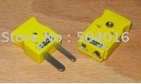
    As the others have said, length doesn't matter at all, but the proper connectors do.

    I use these: Mini K type connectors.

  7. #7
    Join Date
    Sep 2008
    Location
    Geelong, VIC
    Posts
    4,442
    Total Downloaded
    0
    Quote Originally Posted by Leo109 View Post

    ..snip..

    By the way, I wouldn't use the Auber exposed tip T/C in a pre-turbo (upstream) situation. I'd only ever use a fully sheathed T/C pre-turbo.

    Ian
    Is that just due to the possibility of the tip breaking off and going through your turbo?

    Steve

  8. #8
    Join Date
    Jan 1970
    Location
    VIC
    Posts
    3,536
    Total Downloaded
    0
    Quote Originally Posted by steveG View Post
    Is that just due to the possibility of the tip breaking off and going through your turbo?

    Steve
    Exposed tips aren't to be used generally in pressurised or corrosive environments.

  9. #9
    Join Date
    Jan 1970
    Location
    Travelling OZ - Back in SE Qld again at the moment
    Posts
    672
    Total Downloaded
    0
    Quote Originally Posted by steveG View Post
    Is that just due to the possibility of the tip breaking off and going through your turbo?
    Steve
    Hi Steve,

    Yes, pretty well. With exposed tip thermocouples, the compressed mineral powder insulation (ceramic-like) is exposed at the tip where the outer metal sheath ends. It's not unknown, especially where there's a lot of vibration (like an engine exhaust manifold?), for bits of the 'ceramic' to fall out and these bits are not kind to turbine blades spinning at >100,000 rpm.

    As Mr 8NW says, (or may we call you by your first name, B92?), exposed tips can also be affected by corrosive gases, including ones with sulphur compounds, but with low-sulphur diesel these days that's probably not a major concern.

    An exposed tip T/C should be OK in a post-turbo installation provided it's a good quality item able to handle the vibrations in an automotive engine. However, IMHO, there's no need to use them just for speed of response. Good quality fully sheathed and insulated tip T/Cs are more than adequate for 'keeping-up' with rapid EGT changes.

    My two cents worth...
    Ian
    Ian &
    Leo - SIII 109/GMH3.3
    Daphne I - '97 Disco 300Tdi Manual
    Daphne II - '03 Disco Td5 Auto

Bookmarks

Bookmarks

Posting Permissions

  • You may not post new threads
  • You may not post replies
  • You may not post attachments
  • You may not edit your posts
  •  
Search AULRO.com ONLY!
Search All the Web!