Page 3 of 3 FirstFirst 123
Results 21 to 28 of 28

Thread: Wiring an EDIC motor and relay?

  1. #21
    Join Date
    Sep 2008
    Location
    Geelong, VIC
    Posts
    4,442
    Total Downloaded
    0
    Quote Originally Posted by Dave_S View Post
    Good idea Steve. There are a few spare spots in some of the plugs so I could run a test light/multimeter to them easy enough. It will be easy to do and can't hurt trying.
    Ideally you'll be able to find one of those twin/triple connectors that you can just plug into. Worst case, you should be able to find something to connect to even if its a case of cut/join/solder into an existing wire. Not ideal, but I know the sort of crap you mean with an old butchered loom. Sometimes you've just got to make it work the best way you can.
    Make sure its either really obvious where its connected to, or make some notes for later down the track or you'll be sorry!!

    Steve

  2. #22
    Join Date
    Mar 2007
    Location
    Brisbane
    Posts
    653
    Total Downloaded
    0
    Will be making lots of notes!

    I recently saw a car with a home made loom, which looked sensational. It had a hidden (but easy access) panel that all the main wires ran through. There was a board for permanently live circuits, another for ignition switched and everything ran off a neat bank of relays. It was all protected by blade type fuses. The guy even had a holder for an A3 sized laminated circuit diagram that he'd made up for the car. The really nice part was that under the bonnet everything looked standard.

    I'd like to do something similar, perhaps using some of the generic components they make for hot rods. With a bit of planning it should be possible to vastly improve on what's there now.

  3. #23
    Join Date
    Sep 2008
    Location
    Geelong, VIC
    Posts
    4,442
    Total Downloaded
    0
    Sounds awesome - got any photos?
    The wiring on mine is the only thing I despise about the whole car as I know its going to bite me in the bum at some stage.
    I've let the smoke out of it twice now, but thankfully nothing too serious yet.

    Would love to rewire from scratch with modern plugs/fuses and everything positioned logically etc, but think it would have to be a ground-up rebuild to work properly.

    Steve

  4. #24
    Join Date
    Mar 2007
    Location
    Brisbane
    Posts
    653
    Total Downloaded
    0
    Sadly I have no photos as yet. I expect I'll see the car again and will try to take some. I think a full rewire would be a huge job and you'd want to do some serious pre-planning. Some in depth reading would help unless you're an auto electrician, which I'm not.

    Then again, at the end of the day it is just a collection of circuits that need to be laid out in an organised, systematic fashion. Plus you would be free from the constraints that accountants and production line assembly methods dictate.

    Aging wiring, especially aging, butchered, English wiring, is never going to be ideal. I reckon a new custom loom would be time well spent.

  5. #25
    Join Date
    Mar 2007
    Location
    Brisbane
    Posts
    653
    Total Downloaded
    0
    Quote Originally Posted by steveG View Post
    Ideally you'll be able to find one of those twin/triple connectors that you can just plug into. Worst case, you should be able to find something to connect to even if its a case of cut/join/solder into an existing wire. Not ideal, but I know the sort of crap you mean with an old butchered loom. Sometimes you've just got to make it work the best way you can.
    Make sure its either really obvious where its connected to, or make some notes for later down the track or you'll be sorry!!

    Steve
    Job is finally done. I did extensive and frustrating testing of every ignition switched wire I could find, but every single one carried some current after the ignition was switched off. I was going to give up and call in an auto electrician to sort it, but decided to take the quicker, practical approach of just breaking the circuit with an on/off switch. It works for now and I'll put it on the list of things to sort out when I rewire the vehicle.

    Only 51 items left on the current list before I can start using it

  6. #26
    Join Date
    Sep 2008
    Location
    Geelong, VIC
    Posts
    4,442
    Total Downloaded
    0
    Good work Dave.
    I'm definitely no auto-elec, but sounds like an issue with your alternator wiring and the alternator output is feeding into the switched side of the ignition somehow.
    What sort of alternator are you running - externally regulated one like a standard Landy setup, or internal reg one?
    What does the heavy output wire from the alternator connect to?

    Steve

  7. #27
    Join Date
    Mar 2007
    Location
    Brisbane
    Posts
    653
    Total Downloaded
    0
    Steve, I'm not sure about the alternator specs, but seriously doubt it is standard Land Rover issue. The vehicle started as a V8. I don't plan to spend any more time on this until I get the vehicle up and running and in regular service. It will do a full rewire in a while and I want to make the loom myself if at all possible. I suspect this little issue will be just one of many I'll have to work through. I reckon I'll need to get a consultant auto electrician to check my work though.

  8. #28
    Join Date
    Jul 2011
    Location
    Yallingup
    Posts
    37
    Total Downloaded
    0

    Edic wiring help

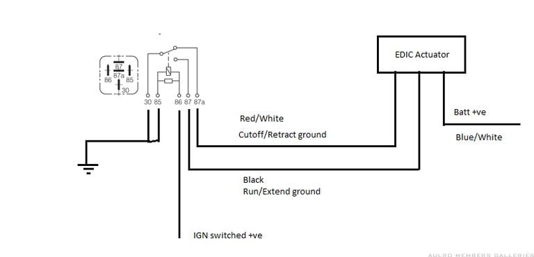
    My actuator has 5 wires (blue, blue/white, blue/yellow, blue/red, black. The original jideco relay is shot. Can anyone let me know wiring diagram for connect to new relay with (30,85,87,88) pins?


    QUOTE=steveG;1771994]Excuse the poor drawing, but here's what I could work out last night without pulling things apart too much.
    Only thing I'm not 100% sure on is the wire colours for the actuator as I have different colours extending the wires to the relay, and the connection plug is hidden in a rubber boot.
    I've used the original Jideco relay, but I've done this diagram to use a standard changeover relay.

    It would be great if you could test out the circuit on the bench and post/PM any corrections so I can amend the drawing.


    As a separate test to confirm which actuator wire is which, with +ve applied to the correct wire, and the other 2 wires to ground, the actuator should repeatedly cycle in-out-in-out ( I think !!).
    Also, if you check the continuity between the wires, you'll find 2 wires that show a circuit, and one not connected to either of the others. The one that isn't connected is one of the ground wires. Apply 12v to the wires that have a circuit and the actuator should move and stop. You should then find that a different wire is open circuit - that one is the other ground wire. The third (common) wire is the +ve supply.

    Steve[/QUOTE]

Page 3 of 3 FirstFirst 123

Tags for this Thread

Bookmarks

Bookmarks

Posting Permissions

  • You may not post new threads
  • You may not post replies
  • You may not post attachments
  • You may not edit your posts
  •  
Search AULRO.com ONLY!
Search All the Web!