1. You also need the panel that goes from the top of the mudguard to the footwell.
2. There is no need to change the brake light setup - the pedal switch will still work and be legal
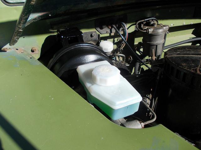
3. Not sure about the Defender M/C, although I think it will work.
4. You also need to use a brake shuttle valve. This is what allows pressure to be applied to both systems even if the shoe adjustment is slightly different. Without it, you will fully apply either front or back brakes, depending which is adjusted up more closely, without any braking on the other circuit. It also contains a switch that is operated if the shuttle valve spool moves fully in either direction, indicating failure of a circuit. This switch needs to be wired to a warning light for the system to be legal.
Hope this helps.
John
JDNSW
1986 110 County 3.9 diesel
1970 2a 109 2.25 petrol


 Reply With Quote
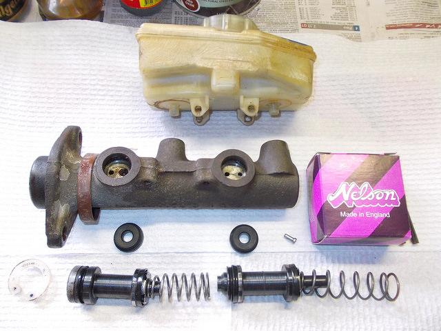

Bookmarks