Hi all,
Earlier this week i had to wire a customers vehicle for Electric Trailer Brakes.
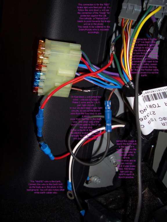
I took a couple of photos & this one was the best with everything in 1 shot.
I will try to explain basically as last time it wasnt to clear!!

Run 4 wires from the Electric trailer brake unit mounted under the steering column or where ever it is mounted to the rear of the vehilce l/h/s 1/4 panel.
WHITE wire is for earth & gets bolted to one of the terminals as u see in the photo.
BLACK wire is for power +ve & is connected to the 30amp circuit breaker & then another black wire from the circuit breaker (other side)gets connected to the thick PURPLE wire from the trailer wiring plug.
BLUE wire is for variable voltage feed to the electric brakes on your towed vehicle. This is connected to the brown wire from the fuse block. This wire is cut 30mm from the fuse block & the fuse block end is then soldered to the black wire in the fuse block(these are 2 park light circuits & we only need 1) The other end of the Brown wire goes to pin 5 which is for electric brake feed.
RED is brake light feed pick up This is connected to the Green/Purple trace wire in the trailer wiring plug.
As per LR instructions a "Diode" must be fitted & this goes between the connection of the red wire to the Green/Purple Kathode facing the electric brake unit.
**On the photo i ran out of blue wire & used another black for the blue wire connection to the brown wire.
When i receive stock of the blue i will replace photo.
Hope this helps some of the crew.
")
")
If the photo is not big enough go to my gallery & view orig size.


 Reply With Quote

Bookmarks