
Originally Posted by
isuzurover

500CFM in sensible units is ~0.24 m3s-1
Re=rho*V*D / mu
Re = reynold's number (see Moody Diagram)
rho = density (of air)
V = velocity
D = diameter
mu = dynamic viscosity of air = 1.81e-05 at 20oC.
For a 3"/75 mm diameter inlet pipe, V=54 m/s and Re = 4.1e5.
That is a reasonable value, however could be slightly lower.
However, when designing an intake, it is much more important to ensure the pipes are as smooth as possible, bends are as large a radius as possible, and transitions are smooth. All of this will likely have much more effect than the diameter of pipe you use.


 Reply With Quote
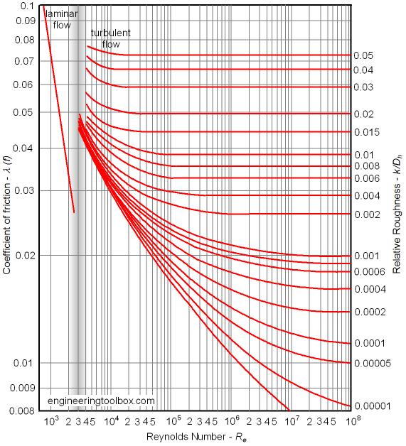

Bookmarks