

 Reply With Quote
Thank you for this. Mine would be quite different, as the gearbox is actually quite some distance behind the driver, who is next to the engine. But I reckon I can do a lot with this.Originally Posted by workingonit


 Wizard
Supporter
Wizard
SupporterBoy, its taken me hours to get to this point!
Screenshot (2).jpgScreenshot (3).jpg
CAD tower computer on and off, reboot, every few minutes - no solution to problem yet. Managed to get an STL file but not allowed on AULRO because of space they take I guess. Was hoping to get the STL on so others could download, take measurements and work their own tailored solution.
The drawings are not complete, some machining done on the fly. Photos will indicate what is missing - the diff lock mechanism was dropped into the photo to show the difficulty of incorporating all the pieces. The gear change stick should more than likely have been behind the diff lock stick. The mechanism was a practice exercise, no accounting for position of diff lock lever, gearbox tunnel cowling, and fact it is too close to dash board - made it before body on chassis - just wanted to see if I could get something working.
Probably the most interesting is the sliding mechanism at the base of the gear stick. Will pull that apart tomorrow and lay it out like an exploded diagram so you can see the relationship of parts. The rest is relatively straight forward, sort of. The four bolts that hold the gearbox lid on are used to support the mechanism.
.P1000455.jpgP1000456.jpg
Ancient Mariner's linkage system is close to the bell housing like my trial, and suits his vehicle (can't recall now what it was). Notice the mechanism this side in his clip and its relationship to CAD diagram one and photo one. On the other side of the box you may just see movement of a rod and hiem joint or ball joint, unlikely cable?
GH010188. VW shifter to Isuzu MSA - YouTube
Dodgybloke shows back and lifted
Isuzu MSA gearbox shifter conversion
LordRover
SubscriberThank you for this. Mine would be quite different, as the gearbox is actually quite some distance behind the driver, who is next to the engine. But I reckon I can do a lot with this.
JayTee
Nullus Anxietus
Cancer is gender blind.
2000 D2 TD5 Auto: Tins
1994 D1 300TDi Manual: Dave
1980 SIII Petrol Tray: Doris
OKApotamus #74
Nanocom, D2 TD5 only.
Wizard
SupporterP1000466.jpgP1000465.jpg
Part 1 the round bar is milled to fit in a sleeve bearing welded to the framework. The round bar is also drilled to take the shaft on item 2.
Item 3 screws onto the threaded end on 2, while the other end engages a linkage.
Item 4 - base of the gear lever - swings in the arms on 1 (ignore the lower hole, a mistake), and also engages the pin in 2.
Will provide more photos on each part and some dimensions.
Item 1 is in the CAD drawing. Item 4 in the CAD drawing is represented as round bar but should be square bar. Item 2 and 3 do not appear in the drawing.
YarnMaster
Supporter
Use the original cable shift like I did on the 6x6 FC. I left it full length and looped it but it could be shortened.
Only downside was the shift was back to front but it did not bother me.
Keith
Wizard
SupporterHi Keith. Have you got pictures on the cable set up, on AURLO anywhere? Or have others posted the same? Cable might be better for Tins, but if persisting with solid linkages would think you just reverse the design, but still the issue of 'upside down' changes you get used to.
Wonder what set up Tins has at the moment - good to know what not to use, if not working so well?
LordRover
SubscriberScreenshot 2024-03-11 at 4.09.00 PM.jpg
When set up properly it works... If the adjustment is out, or there is a worn Rose joint it becomes a total pig.
I appreciate it's not a simple task.
JayTee
Nullus Anxietus
Cancer is gender blind.
2000 D2 TD5 Auto: Tins
1994 D1 300TDi Manual: Dave
1980 SIII Petrol Tray: Doris
OKApotamus #74
Nanocom, D2 TD5 only.
YarnMaster
SupporterI think I had a thread on here somewhere but have not found it yet.
This is one from another forum but some of the first photobucket photos have gone.
900 Club Forum - Login
Keith
Wizard
SupporterIs that the best you can do Scotty? Aye, captain!
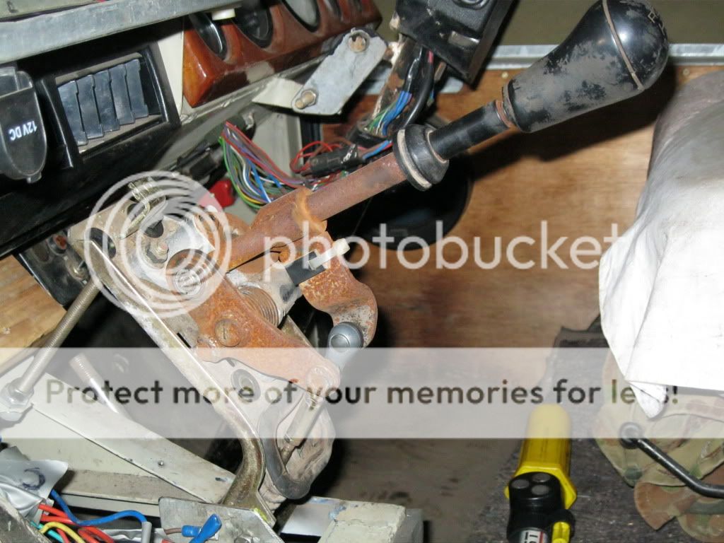
Took me a minute of craning my neck before I decided to copy and rotate the diagram.
I assume, given the gear stick is ball mounted, that it moves side to side and forward and backward. Not 100% sure whether the crank in the rod is simply to get around something or plays a role in leverage when rolled or push/pulled?
My guess is the gear stick rotates the bent rod around it's long axis to select gear clusters using the shaft sticking out of the top of the gear box at the front.
The gear stick pulls and pushes the bent rod along its long axis to select individual gears from a cluster, using the shaft that sticks out of the side of the box.
Did the shift mechanism come with the OKA Cummins? engine or as part of an Isuzu conversion? Has the shift only become difficult with wear or has it always been like that? Is it too hard to find some of the parts?
My design, and other like Sheldon and Ancient Mariner, split the two paths at the gear lever, left and right. The OKA design splits the path at the end of the bent rod. See your problem with potential wear in the ball joint for the gears stick, the rose joints and the universal. Any design like mine, Sheldons or Ancient Mariners would require being mounted to the front of the gearbox rather than on top or rear of the gearbox. The spring bits go forward of the gear stick and the linkages go rear of the gear stick.
YarnMaster
SupporterI see one has to log in to view.
Not many pics of the gearbox anyway.
The cable shift on the g,box just came up to the dash where I put the back to front gear lever. It was simple really. I still have a spare cable shift in the shed.
LordRover
SubscriberBeen using this forum for nearly 14 years and I still don't know why it does that.
Pretty good guesses. Except the OKA is stock, with a Perkins Phaser, and a five speed Spicer. The rod is cranked to avoid the bell housing, as the shift levers are quite close to the engine. The rod itself I think is part of the issue, as it is quite heavy. My OKA is 30 years old, and I don't know what it was like from new, but the gearbox and engine were both new replacements a few years back. One would think they might have given the linkages some attention then. I have only ever driven one other stock OKA, and it was far better, but still awkward, and I am no stranger to unusual gearbox setups. I think some people would consider mine to be undriveable, but I manage.
Parts aren't as difficult as you would imagine. OKA wasn't financial enough to have much bespoke stuff, so a lot came from other truck builders. Most driveline stuff is American, such as gearbox, transfer case and axles. Some internal stuff, like column and associated switchgear is harder, as it is Leyland. I do think the gearshift was designed in house, the parts, such as the rose joints, are generic.
I see now that my initial enthusiasm over your design, as mentioned in the other thread, was probably misplaced, as it is quite different to what I need. But it's well thought out and I still wonder if I could take some of it for mine.
OKA is not my main priority at the moment, but your mention of designing a shift got my interest. If I was rich it would get a 6 cyl Perkins ( not a Cummins 6BT like others have ) and an Allison.
Last edited by Tins; 12th March 2024 at 08:44 AM.
JayTee
Nullus Anxietus
Cancer is gender blind.
2000 D2 TD5 Auto: Tins
1994 D1 300TDi Manual: Dave
1980 SIII Petrol Tray: Doris
OKApotamus #74
Nanocom, D2 TD5 only.
| Search AULRO.com ONLY! |
Search All the Web! |
|---|
|
|
|


Bookmarks