SC40-LR Plug-&-Play KIT installation instructions.
The SC40-LR Plug-&-Play Kit is $199 from Traxide, is specifically made for the Discover 3 and Range Rover Sports.
For additional Info about this kit, you can either PM me ( drivesafe ) here or phone me on - 07 5569 2557
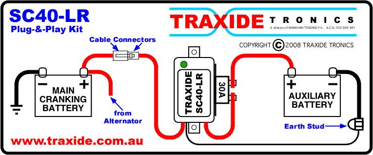
HOW THE SC40-LR PROTECTS THE BATTERIES
The primary objective of the SC40-LR is to protect the vehicle’s main ( cranking ) battery from being discharged bellow a point which the battery would not be able to start the vehicle. But as most vehicle cranking batteries are capable of supplying some of there stored power for other uses and still have enough charge left to be able to start the vehicle, the SC40-LR also allows this additional power to be used.
So while there is extra power available at the main battery the SC40 shares the load between the main battery and the auxiliary battery and in doing this the operating time for the accessories running off the auxiliary battery is extended but at the same time the SC40-LR will still automatically safe guard main battery from being over discharged.
The second function of the SC40-LR is to make sure the main battery, after the vehicle is started, has a sufficiently high enough charging voltage before starting to charge the auxiliary battery(s).
Another function is to protect the auxiliary battery should the main battery fail, the SC40-LR will isolate all batteries and when it come time to start, the auxiliary battery may be used to just start the vehicle.
SPECIAL SAFETY NOTICE :- Once the SC40-LR is installed, should you have to disconnect either the Main ( Cranking ) battery or the Auxiliary Battery, first disconnect the plug and sock connection in the cable running from the Main ( Cranking ) battery and the SC40-LR Control module, this will avoid damage being caused if the positive battery lead is dropped and contacts any vehicle earth.
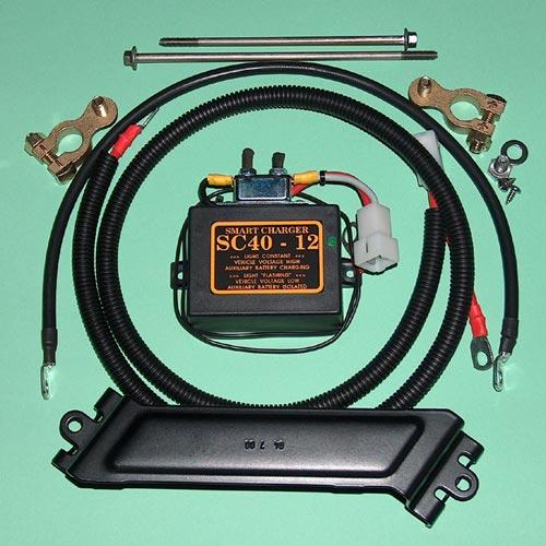
The kit contains the following :-
SC40-LR Control Module with pre-wired Circuit Breaker mounted on the side.
Red Battery fitted with 8mm eye terminal, 2 pin plug, covered with Black Split Tube.
Black Auxiliary Battery Earth Lead.
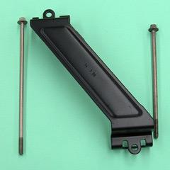
Auxiliary Battery mounting Bracket.
2 x Long Bolts for Auxiliary Battery mounting Bracket
2 x Battery Terminal Clamps
1 x 8mm Stainless Steel Bolt and Stainless Steel Washer.
2 x Alcohol Swabs
4 x Wire Ties.
PRE INSTALLATION REQUIREMENTS.
If you have just turned your Ignition off, make sure the Park Brake is applied and the key is removed from the ignition.
Pull the bonnet release and open the bonnet.
Remove both Battery Compartment covers. This is done by first releasing the 2 tabs at the front of both covers and then lift the front edge of the covers and then twisting and remove the covers.
Now, go back to the cab and check that the Park Brake Light is out. This is important, while the Park Brake Light is on, the vehicle’s computers are still going through their Shutdown routines and these Shutdown routines MUST BE COMPLETED before you work on any electrical components on this vehicle.
MOUNTING THE HARDWARE.
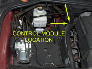
Go to the Auxiliary Battery Compartment and follow where the wall of the compartment runs beside engine to where it comes to an indent just before the wall reaches the back of the engine bay. This is where Control Module is to be fitted.
Before fitting the control module, make sure the surface that the control module is to be fitted to is clean and dry. Even if the surface appears to be clean, the surface in the area where the module is to be fitted should be wiped with a damp cloth and then with a dry cloth and the with the alcohol swabs provided in the kit.
It is important that the mounting area is clean, dry and free of any greasy materials.
SPECIAL NOTE :- for LEFT HAND drive vehicles, the MODULE will be mounted in the battery compartment on the driver’s side of the vehicle.
The back of the control module has industrial grade double sided tape on it, DO NOT remove the the peel away backing from the tape just yet.
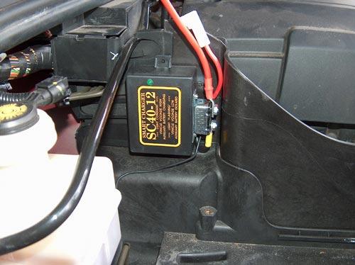
Take the Control Module and position it in the indent as low as possible. Position the module so the LED at the top and the circuit breaker is facing towards the front of the engine bay and resting against the front edge of the compartment’s indent.
You may find a white plastic mounting block fitted to the inside of the D3’s Auxiliary Battery Compartment wall, in the position where you are going to mount the SC40-LR control module. Simply twist this white plastic block 90 degrease and remove it.
Once you are satisfied that the module is in the correct location, remove the peel away backing from the double sided tape and firmly press the module in place.
Once it is in place, it is there to stay so make sure you have it positioned correctly.
SPECIAL NOTE :- for LEFT HAND drive vehicles, the MODULE will be mounted in the battery compartment on the driver’s side of the vehicle.
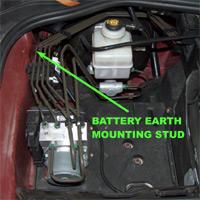
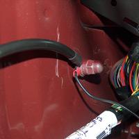
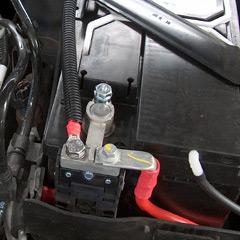
On the inner guard side of the Auxiliary Battery Compartment, towards the rear of the compartment, locate the Battery Earth Mounting Stud, fixed to the body at the back of the Battery compartment. You may need a torch to locate it.
SPECIAL NOTE :- for LEFT HAND drive vehicles, the EARTH NUT will be on the driver’s side of the vehicle.
CAUTION :- You will need to unscrew the nut from the Earth Mount. Make sure you keep a firm grip on the nut because if you drop it down the back of the Battery Compartment you will have a hard time retrieving it.
Take a 13mm spanner, loosen the nut and remove it.
On either end of the thick Black Earth Lead is an eye terminal, one has an 8mm eye terminal and the other has a larger 10mm eye terminal.
Fit the 10mm eye terminal to the Battery Earth Mounting Stud, also place the 10mm eye terminal on the end of the thin Black wire coming from the Control Module and also fit the eye terminal on the end of the cable going to the rear, onto the stud as well and replace the nut. Make sure the nut is secured tightly as it is very difficult to get at once the battery is in place.
CAUTION :- With the nut in place, make sure the black wire coming from the control module is pushed all the way to the back of the battery compartment so that when the battery is fitted in place, it will not sit on the black wire.
Also make sure the thick Black and Red cables are pushed out of the way to allow you place the battery in the compartment and still reach the cables
PLACING THE BATTERY
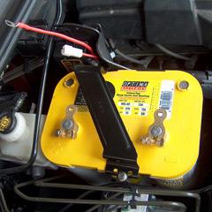
The battery needs to be fitted with the battery’s positive terminal towards the back of the Battery Compartment, so make sure when you pickup the battery, you have it the correct way round to save you trying to turn it once you have it in the engine bay.
Get the Battery Bracket and two long bolts from the kit and secure the battery in place.
In the kit are two Battery Terminal Clamps, one for the positive terminal and one for the negative terminal. On the underside of each clamp is a bolt, remove the bolt and then fix the clamps to the correct battery terminal and tighten the securing nut and bolt.
DO NOT CONNECT THE BLACK EARTH LEAD AT THIS TIME.
SPECIAL NOTE :- When fitting the battery in LEFT HAND DRIVE vehicles, the bracket may come in contact with the terminals on some types of batteries.
For this reason, the RED cable coming from the SC80-LR module is longer so that the battery in LEFT HAND DRIVE vehicles can be fitted with the Positive terminal towards the front of the battery compartment and the battery bracket can then be fitted without coming in contact with either battery terminal.
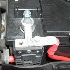
Take the Red Battery Cable covered with the Black Split Tube from the kit and go to the other side of the engine bay, to the Cranking Battery.
On the clamp on the Cranking Battery’s positive terminal is a threaded hole. On one end of the Red Battery Cable that came with the kit is an 8mm eye terminal, take the Stainless Steel Bolt and Washer from the kit and secure the Kit’s Red Battery Cable to the hole in the Cranking Battery’s positive terminal with the Stainless Steel Bolt and Washer using a 13mm spanner.
Lay the Red Battery Cable back along side the edge of the Cranking battery, to the rear of on Cranking battery Compartment then across the rear edge of the engine bay towards the Auxiliary Battery Compartment.
Coming from the SC40-LR module is a Red cable with an 8mm eye terminal fixed to the end of it, take this cable and bolt the eye terminal to the Auxiliary battery’s positive terminal clamp using one of the terminal clamp bolts.
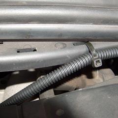
Take two Wire Ties from the kit and go the the rear edge of the engine bay and on either side, along the edge where you laid the Red Battery Cable, you will see short slots in the ledge along the back of the engine bay.
CAUTION :- Some D3 models ( petrol engine ) have a thin black pipe just under this ledge, gently move this pipe back a few millimetres so you can thread the wire tie through the slot and around the Red Battery Cable BUT NOT AROUND THE THIN BLACK PIPE.
Secure the Red Battery Cable on both sides of the engine bay with the wire ties.
Now go to the Auxiliary battery’s negative terminal and connect the Black Earth Lead to the negative terminal using the other Battery Clamp bolt.
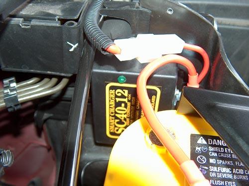
Now push the plug on the Red Battery to Battery Cable coming from the cranking battery, into the socket coming from the SC40-LR.
Once you have plugged the connectors together the Green LED on the SC40-LR will be on and flashing.
INSTALLATION OF THE DUAL BATTERY SYSTEM IS NOW COMPLETE.
Before putting the Battery Compartment Covers back on, test the the system.
The Green LED on the SC40-LR will be flashing. This indicates that the SC40-LR has power but the Cranking Battery voltage is below the CUT-IN voltage level.
Start the motor and let it idle.
After a few seconds to a minute at most, the Green LED will glow constantly. This indicates the Cranking Battery voltage has risen above the CUT-IN voltage level and the SC80 has now connected the two batteries together.
If all is working correctly, turn the motor off and replace the two Battery Compartment Covers back on and your ready to go.[040908]
THIS KIT IS MANUFACTURED IN AUSTRALIA AND SUPPLIED BY
TRAXIDE TRONICS
TRAXIDE

 OldBushie
 Posting Permissions


 Reply With Quote
Bookmarks