
")


 Reply With Quote
Ali I haven't been able to find any such kit - can you point me in the right direction ?

 TopicToaster
Or you can do what I have done to my two defenders and buy the kit from eBay. Pretty cheapOriginally Posted by alexturner

I just put the bulbs straight in no messing around. Although I did not remove the green tints , but need to drill them out on a 300tdi and still alot better lights with them in
Sent from my iPhone
95 300 Tdi Defender 90
99 300 Tdi Defender 110
92 Discovery 200tdi
50 Series 1 80
50 Series 1 80
www.reads4x4.com
Major Part of the Heart and Soul of AULRO
SubscriberAli I haven't been able to find any such kit - can you point me in the right direction ?
It's not broken. It's "Carbon Neutral".
gone
1993 Defender 110 ute "Doris"
1994 Range Rover Vogue LSE "The Luxo-Barge"
1994 Defender 130 HCPU "Rolly"
1996 Discovery 1
current
1995 Defender 130 HCPU and Suzuki GSX1400
TopicToaster
Here you go
http://item.mobileweb.ebay.com.au/vi...d=350372098002
Sent from my iPhone
95 300 Tdi Defender 90
99 300 Tdi Defender 110
92 Discovery 200tdi
50 Series 1 80
50 Series 1 80
www.reads4x4.com
TopicToaster
for led replacement for the instrument lights, search ebay for a t10 led.
here is what you want if you are after blue light.
http://www.ebay.com.au/itm/2-x-Car-T...item415389a7ef
Last edited by slug_burner; 23rd May 2011 at 08:26 PM. Reason: added search result link
TopicToaster
To check your earthing, run a nice wire back to your battery terminal. Use your jump lead with a short wire clamped to one end and coonect short wrire to instrument with suspected poor earth. Then you will know if you have a poor earth problem to fix.
Master
SubscriberI did all that, then out of frustration i invested in a 500 Ohm potentiometre. I connected the 12V power supply to the power terminal on the gauge and then place the 500Ohm pot between the sender terminal and earth (ground). Regardless of the pot's value the gauge would still rise, though when wound to 500Ohm (or higher resistances) it would climb faster. I think I have two dead gauges...
TopicToaster
have looked at workshop manual, fuel and water temp gauge share the supply on a green wire. fuel gauge has other side going off on a green black trace wire.
green/black goes back to fuel sender.
the tank sender is a variable resistor one end and wiper connected to ground, the other end back to the gauge.
temp sender is depicted in the same manner, wire connecting sender and gauge is green/white close to the gauge then on the otherside of the connector it goes to green/blue.
the green/black from fuel gauge also goes to the low fuel level unit.
for some reason I think that the sender are 180 ohm units although I was not able to confirm it.
The gauges do have a damped response so once you swing your test pot to read full I expect the gauge to climb.
Did you disconnect the sender when you used your test pot or did you throw it in parallel?
A little unfortunate/unlikely for both gauges to go at the same time!
TopicToaster
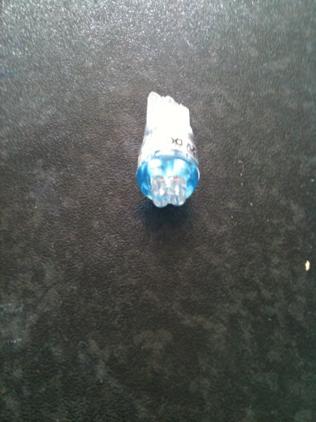
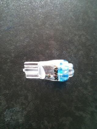
Vlad. easier way to do it is to go to Jaycar and buy 4 "led globe T 10 wedge 4 x blue" cost $2.85 each
Then put them straight into you defender
They look like this
Ali
95 300 Tdi Defender 90
99 300 Tdi Defender 110
92 Discovery 200tdi
50 Series 1 80
50 Series 1 80
www.reads4x4.com
Master
SubscriberDidn't wire it in parallel wired it just as you described, then took the gauge out and wired it using the battery directly as the power source. As I bought my car with a non-working speedo I now have not one working gauge in my panel
I'm not sure where to go from here.
TopicToaster
FIrstly I would ensure that the gauges are ok or rs. Having got the gauges out I would put them on a bench with a linear pot (not log) to ensure that you getting a good range acroos the pot. Also check what the resistance of your fuel and temp senders are and match your pot as close as you can other wise you will also lose range.
When your measuring the sender resistance do it both from the wire at the dash and then do it at the sender bypassing the wiring. You should get the same readings if all is ok.
Other technique is to compare with a known good vehicle.
After that you either need some new gauges or you need to find the fault in the vehicle wiring.
 Posting Permissions
| Search AULRO.com ONLY! |
Search All the Web! |
|---|
|
|
|

Bookmarks