

 Reply With Quote
Thanks Spud!Originally Posted by spudfan

Good to know there are other options. I'll try and seal it with an appropriate amount of RTV silicone first, but if that fails I'll look into one of these.
Alternatively, I could always cut my own I guess.

 Wizard
Supporter
Wizard
SupporterExcellent stuff. My daughter has a 90 300 tdi and I got a sump gasket for it. This is where I got it from on EBAY but there are other suppliers there too. No oil seeps since it's been fitted.
Landrover Defender 300 TDi Sump Gasket | eBay
TopicToaster
Thanks Spud!
Good to know there are other options. I'll try and seal it with an appropriate amount of RTV silicone first, but if that fails I'll look into one of these.
Alternatively, I could always cut my own I guess.
[B][I]Andrew[/I][/B]
[COLOR="YellowGreen"][U]1958 Series II SWB - "Gus"[/U][/COLOR]
[COLOR="DarkGreen"][U]1965 Series IIA Ambulance 113-896 - "Ambrose"[/U][/COLOR]
[COLOR="#DAA520"][U]1981 Mercedes 300D[/U][/COLOR]
[U]1995 Defender 110[/U]
[SIGPIC][/SIGPIC]
TopicToaster
Don't get me wrong, I'm a firm advocate of "RTFM" as a foundational start point for any work you do if you're not expert at it already. Sometimes, however, the manual is more unhelpful than it is worth.
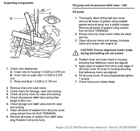
In the case of 300Tdi oil pumps, the official Land Rover manual (LRT0070ENG) is utter ****.
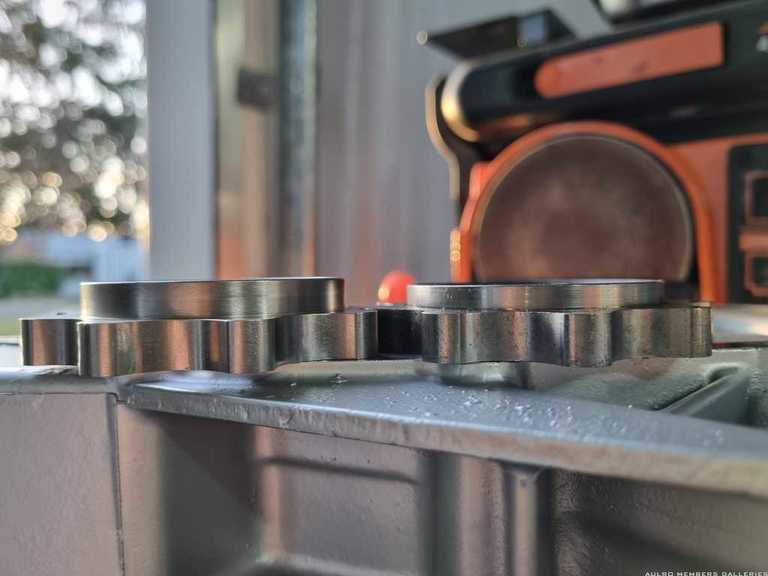
For those unfamiliar with it, the timing case on the 300tdi is actually a pump. If you look at the back of the casting, between the webs near where the injector pump bolts, you will see the brand "HOBOURN" on it - an OEM supplier of lubrication pumps to much of the British auto industry.
Not just a casing to house your valve smashing snappy-strap; it actually forms the running surface for the oil pump rotors and incorporates the intake, compression, and outlet chambers. Like any critical components that go round and round fairly hastily, it is subject to quite fine tolerances, which are outlined in the manual, along with a procedure for measuring them.
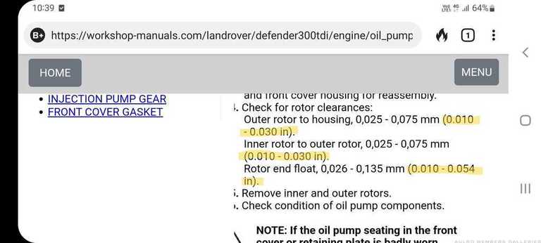
Now this is all well and good, but the specified tolerances between the rotors is allegedly 0.025 to 0.075mm.
That is between one-quarter and three-quarters of the thickness of a piece of paper.
Incidentally, the lower range is smaller than my smallest feeler gauge anyway, but when I went to check it with an absolutely humongous 0.08mm gauge, it was absolutely miles off.
Perplexed, I presumed that one or both of two things had occurred. I was measuring it incorrectly, or my pump was incredibly worn.
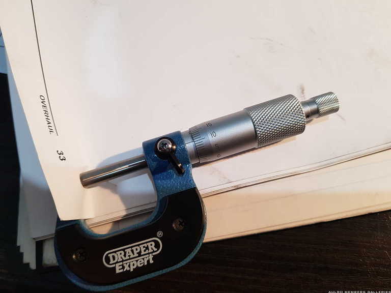
I double checked the manual, double checked my gauges, checked their thickness with the outside micrometers, checked the housing, watched some YouTube of some generally reliable sources and couldn't for the life of me figure it out.
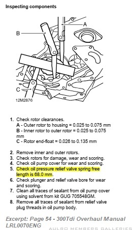
Until I came across a copy of the 300Tdi Overhaul Manual that included imperial measurements for those who still live in black and white.
Thus:
Now it's been a while since I laid spanners to the Series fleet and so my brain is largely metricated, but if memory serves me right, 0.01" is a lot bigger than 0.025mm. Turns out... it is 0.25mm. Seems like too good a coincidence to me. Evidently someone put a decimal place in the wrong spot and it has just never been updated.
Armed with this new knowledge, I did some targeted searching to see if other people had encountered this problem. Turns out, it's a thing. Additionally, the manuals assertions that the pressure relief valve spring free-length is 68mm is also bollocks, as is the instruction to apply sealant to the oil pump cover plate. Regarding the latter, there was none on mine when I dismantled it, it seems that there is none on anyone else's either, and I can't see how the end-float tolerances (even the correct ones) required can possibly lend themselves to essentially being determined by a vague smear of sealant on the running face/cover.
That said, whilst everything measured up okay against the new seemingly correct values, it is irrelevant because the rotors are junk.
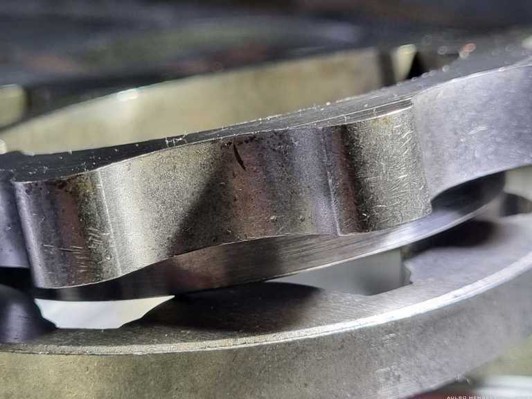
Clearly some small bits of metal have been munched through the pump over the years - probably from the main and big-end bearings, and both the inner and outer rotors are riddled with small divots and gouges on all faces.
The cover plate has some very light scoring in it but nothing much. I'll get it surface ground anyway to get it perfect again.
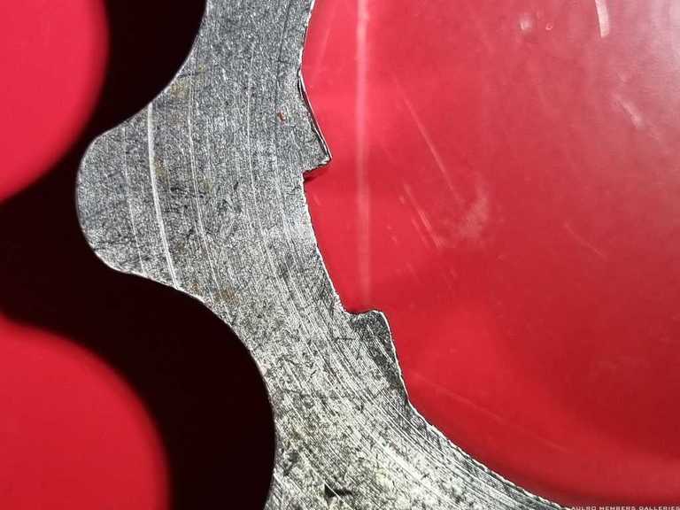
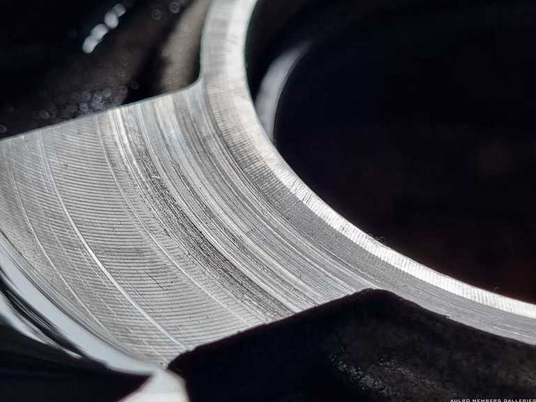
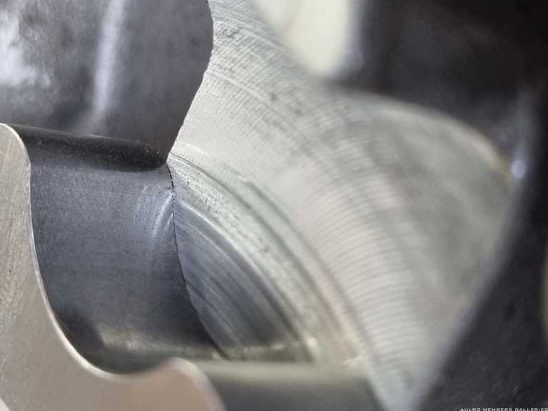
More perplexing though, was the condition of the pump case itself. These are expensive and at present, hard to find it seems, so I didn't relish the thought of replacing it. There is scoring under where the outer edge of the inner rotor runs, and although not overly deep, it's definitely there and you can feel it with your finger nail. This photo makes it look terrible as it's a macro shot: (it doesn't appear as bad in real life)
After doing some more reading and seeking out pictures of other peoples cases, it seems my wear is on the lower end of the spectrum of what I could find. It also wasn't giving trouble as best I could tell, as my engine didn't fail.
I think I am going to live with it.
With new rotors and a fresh running surface on the cover, it should have very little adverse play, if any, and I suspect that the light grooves in the soft aluminium case will not transfer to the steel rotors. Additionally, the wear is on a surface that is perpendicular to the momentum of the rotors, so it's not like they're going to flog against it.
As always, I'm happy to turn this over to the brains trust. Anyone have any experiences of 300Tdi oil pumps to share?
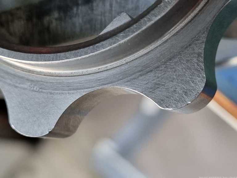
As a bonus finding, the flat on the inner rotor that corresponds with the "wear mark" on the crank, seems to have worn substantially flatter than its comrade on the non-thrust side.
[B][I]Andrew[/I][/B]
[COLOR="YellowGreen"][U]1958 Series II SWB - "Gus"[/U][/COLOR]
[COLOR="DarkGreen"][U]1965 Series IIA Ambulance 113-896 - "Ambrose"[/U][/COLOR]
[COLOR="#DAA520"][U]1981 Mercedes 300D[/U][/COLOR]
[U]1995 Defender 110[/U]
[SIGPIC][/SIGPIC]
Wizard
SupporterGreat write up Andrew. Thanks so much
Andrew
1998 Landrover Defender 300Tdi 130 HCPU Expedition
1972 Peugeot 504 Sedan - Daily Driver
TopicToaster
300Tdi oil pumps - part 2 of at least 3.
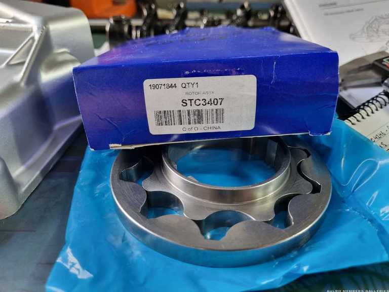
After condemning my oil pump rotors, I ordered a new set from a reputable supplier. For those interested, the current part number is STC3407 - this is for a complete set including both rotors, and replaces the individual part numbers in the parts catalogue.
I was a little wary when a blue box arrived, as these are typically synonymous with a certain parts company that specialises in rather variable quality components. Encouragingly, their logo was absent, but less encouragingly the label specifies the country of origin as one that... also is typically synonymous with rather variable quality components. Measuring and comparing between the old and the new identified a few surprises.
Curiously, the running flange that sits inside the central hole on the new pump is a full 2mm longer than the original. That is to say, the new one sits deeper into the crankshaft hole. The profile of the lobes of the old and new inner and outer rotors was 9.62mm, however the total height of the old inner rotor was 14.74mm compared to 16.74mm for the new one.
I suspect this isn't much of an issue in itself - it is still well clear of the oil seal and if anything, the broader running surface may spread the wear and reduce movement - however remember that little wear-spot on the crankshaft? Well that was perfectly sized to the drive-flats on the old pump, and I'm not sure that I want to disturb it by having the pump run on the 2mm edge where the broader flat sits beyond the wear. At best, it will wear the extra 2mm down to match, putting bits of crank into my oil as it goes. At worst, it will concentrate the force onto that much smaller contact patch and potentially damage the inner rotor and/or the crankshaft.
Test fitting the new rotors in the housing raised more questions than it answered.
The outer rotor to housing clearance was within spec at 0.33mm, although curiously this was slightly more clearance than the old one at 0.28mm. Neither are far off the 0.25mm (0.10") minimum.
The inner rotor to outer rotor clearance is considerably tighter than than the lower value derived from the imperial book (0.25mm / 0.10") and even more considerably looser than the metric book upper value! (0.075mm). The new rotors measured at 0.13mm. Curiously, the old ones were not in spec either at 0.18mm. WHAT?!
The end float for the new rotors was 0.08mm and the old ones 0.10mm. Both within specification I guess, if you assume that on this occasion the metric book was correct with its range of 0.026mm to 0.135mm.
I'm really getting the idea that despite all the guff about these being a vitally important piece of precision engineering, they are actually just two lumps of fairly unfussy metal that as long as they have vaguely enough clearance between them, they'll keep squooging oil around at whatever meagre psi pressure these old donks need to keep chugging. (25psi at idle, apparently). The fact that the tolerances on the original one don't line up with the book - which itself doesn't line up with the other book - suggests that trying to get this done right is probably more down to supposition rather than micrometry.
Spinning the rotors in the housing though, they felt a bit grabby. At first I thought it was just due to them being dry, but then I noticed it was only as certain lobes passed over the running surfaces of the alloy housing. Pulling them out again and looking closely, they have distinct defects in the edges. Looking in the pump case, there is evidence that even by hand, these were removing filings from the aluminium. Thank god I didn't fit them.
All in all I think these new rotors are junk also. I might look to return them and see if I can get a better quality item that is the same dimensions as the original.
Who knew there was so much to know about these things, and so little consensus or information about what the answers actually are!
[B][I]Andrew[/I][/B]
[COLOR="YellowGreen"][U]1958 Series II SWB - "Gus"[/U][/COLOR]
[COLOR="DarkGreen"][U]1965 Series IIA Ambulance 113-896 - "Ambrose"[/U][/COLOR]
[COLOR="#DAA520"][U]1981 Mercedes 300D[/U][/COLOR]
[U]1995 Defender 110[/U]
[SIGPIC][/SIGPIC]
TopicToaster
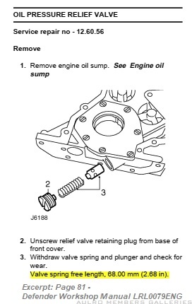
While I'm at it, oil pressure relief valve springs seem to suffer from the same confusion and misinformation.
The 300Tdi overhaul manual specifies that the free-length of the oil pressure relief valve spring should be 68mm
So does the Defender Workshop Manual on Page 81:
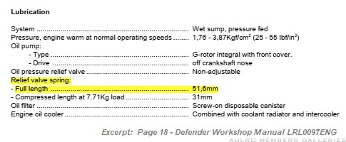
The problem is, that 63 pages earlier in the latter manual it specifies the free length as being a very specific 51.6mm
So clearly one of these is wrong.
Maybe, but as the Mexican girl in the well-known taco advertisement says: "por que no los dos?" ("Why not both?")
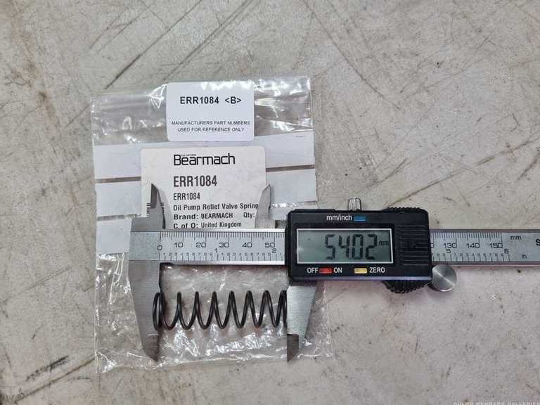
Hence:
My brand new spring is neither - it is 54mm. Reading around, it seems that this is the norm.
Fellow AULROvian ("Pawl") reported similar confusion back in 2007, here:
Oil relief spring 300Tdi
His allegedly genuine new part was substantially shorter again at only 43mm, which is shorter than the free-length of my used one (44mm)!
Another contributor ("2stroke") to the same thread seems to have received a part that agrees with my new one:
Another mystery. I figure the new one will be better than my old one, regardless of what it is meant to be, and the old one seemed to be doing fine as best I could tell. So, it's going in.
[B][I]Andrew[/I][/B]
[COLOR="YellowGreen"][U]1958 Series II SWB - "Gus"[/U][/COLOR]
[COLOR="DarkGreen"][U]1965 Series IIA Ambulance 113-896 - "Ambrose"[/U][/COLOR]
[COLOR="#DAA520"][U]1981 Mercedes 300D[/U][/COLOR]
[U]1995 Defender 110[/U]
[SIGPIC][/SIGPIC]
TopicToaster
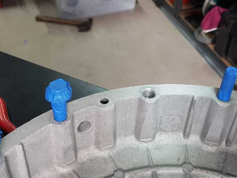
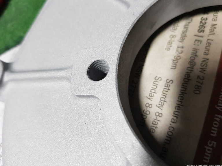
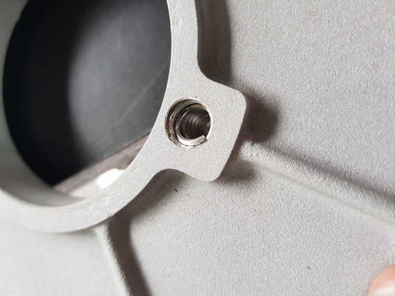
Perhaps unsurprisingly, a number of the threads in various aluminium components have either stripped, or are on their last threads. Since I've got it all apart and I have a helicoil kit I thought this might be a quick and simple fill-in job.
Spoiler alert: It wasn't.
Most of the stripped threads were in the flywheel housing, from the bell-housing bolts being over-torqued. Additionally, the threads in the timing cover where the AC belt tensioner bolts on were also barely hanging in there.
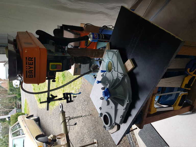
I haven't really done a lot of helicoiling before, so I put a bit of effort into setting up my work in the drill press to ensure I got everything nice and straight. This may have been overkill, but I've always said that overkill is my second favourite type of kill.
First up, I bolted a piece of formply onto the deck of the drill with countersunk bolts so I could have the fairly large components sitting securely and squarely in place.
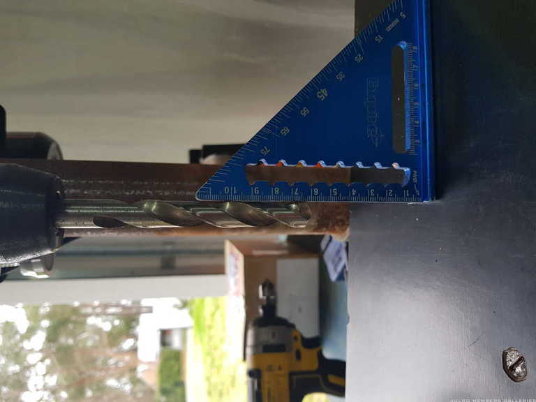
Then, I used a square to adjust the whole platform to be square to the chuck as best as I could. I didn't have anything better than a drill bit to line up against, but as much as it pains me to admit I'm not building a space shuttle here and this will get me set up with more-than-adequate accuracy.
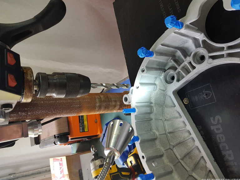
From here, it's just a matter of drilling out the old threads to the appropriate size: (the bit came in the set)
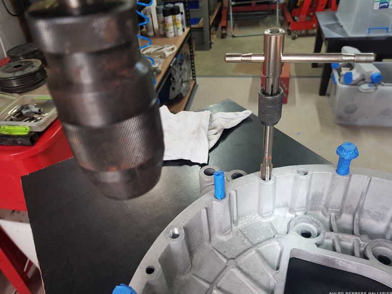
Then tapping them out to the OD thread of the helicoil:
Then attempting to screw in the helicoil and buggering it up:
Each time I attempted to insert a helicoil, it would skip a thread and end up tracking only through every second thread. After some head scratching, I decided that the cheap insert tools were at least a contributing factor. They are much smaller than the ID of the helicoil and hence allow it to compress in, aided by the direction of winding pulling the end of the coil towards the centre of the hole.
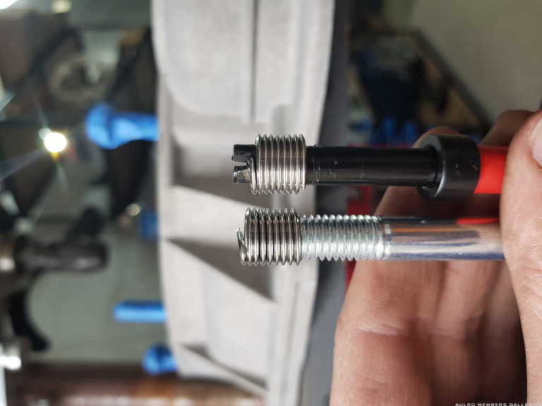
Looking online at some of the more expensive tools, they seem to often use a threaded insert tool that supports the coil in what will be it's final thread spacing and diameter, so I took the Dremel to a spare bolt and cut a slot in the top of it and tried that.
Success! This worked much better, although the bolt did not hold the insert drive-tang as securely. I might talk myself into buying a higher quality helicoil set, as this took way longer than it should have and I had to evict many wonky helicoils with needle-nose pliers after failed insertions.
I got most of them done at least, but still two more to go. If I buy a new kit, I'll post up a comparison.
[B][I]Andrew[/I][/B]
[COLOR="YellowGreen"][U]1958 Series II SWB - "Gus"[/U][/COLOR]
[COLOR="DarkGreen"][U]1965 Series IIA Ambulance 113-896 - "Ambrose"[/U][/COLOR]
[COLOR="#DAA520"][U]1981 Mercedes 300D[/U][/COLOR]
[U]1995 Defender 110[/U]
[SIGPIC][/SIGPIC]
TopicToaster
Much of what I've been doing for the last few weeks has been peripheral stuff whilst I wait for my block (and cam, crank, and pistons) to come back from the machine shop. Sorry for the lack of real engine rebuilding - hopefully next week I'll be able to start getting things back together.
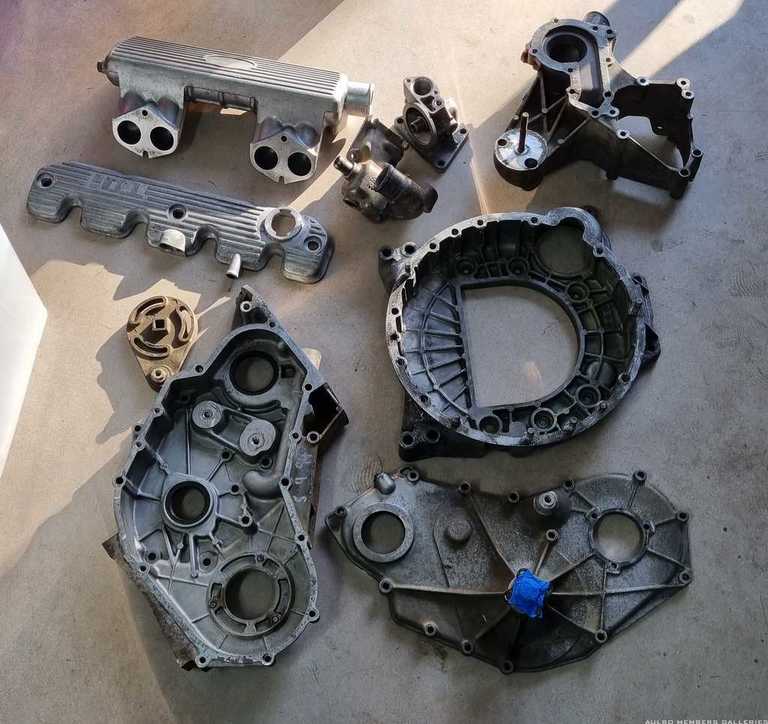
Looking at all the aluminium componentry, it is showing it's 28 years of age and frankly; looks scabbier than a bat's arse. This was AFTER they had been pressure washed and scrubbed in the parts washer...
After talking to a well-regarded media blasting place, they felt that the corrosion required some slightly more aggressive tactics, whilst also balancing the necessity to avoid blasting the alloy to bits and also minimising retained product. The result was that the finish would be dull, although would form a good surface for painting. I'm sorry to report that I don't recall what exactly he blasted it with.
I decided that a coating of high quality ceramic engine enamel would probably look more consistent and be easier to keep clean anyway, so went with it.
$200 later and all the parts came back looking very clean.
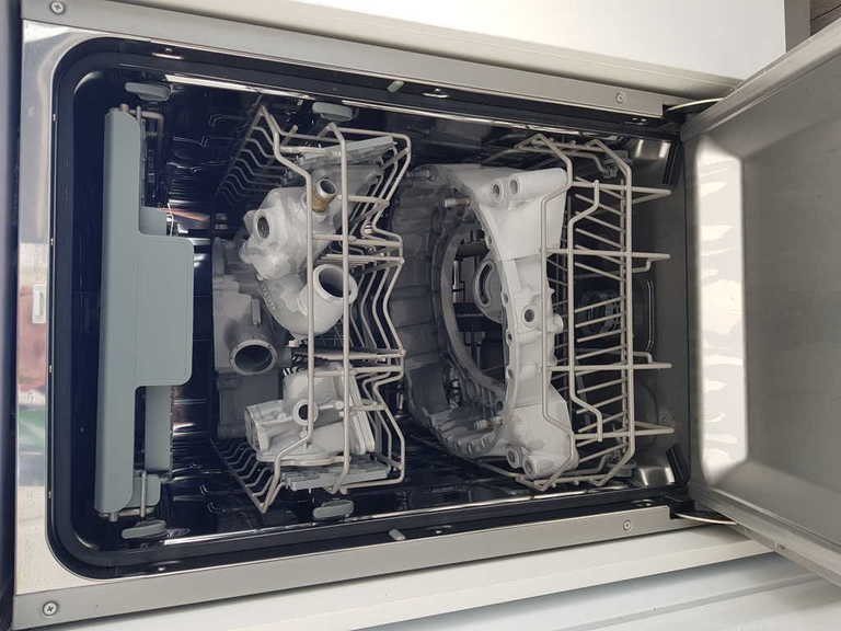
In a moment of paranoia about retained media in the alloy working its way into my engine, I stuck them into the dishwasher for a hot wash. To be honest, I need not have bothered. Hosing them off was surely fine and after the washing I noticed the parts developing white spots where they wanted to start corroding. For the remainder of the parts I just flushed them thoroughly with the hose.
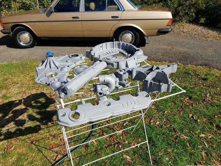
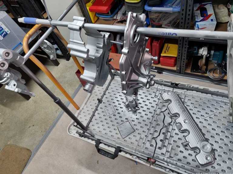
After giving them a week to fully dry out, they each got two coats of ceramic engine primer and three coats of aluminium-look ceramic engine enamel. I used the DupliColor product and was very happy with the finish and how it went on.
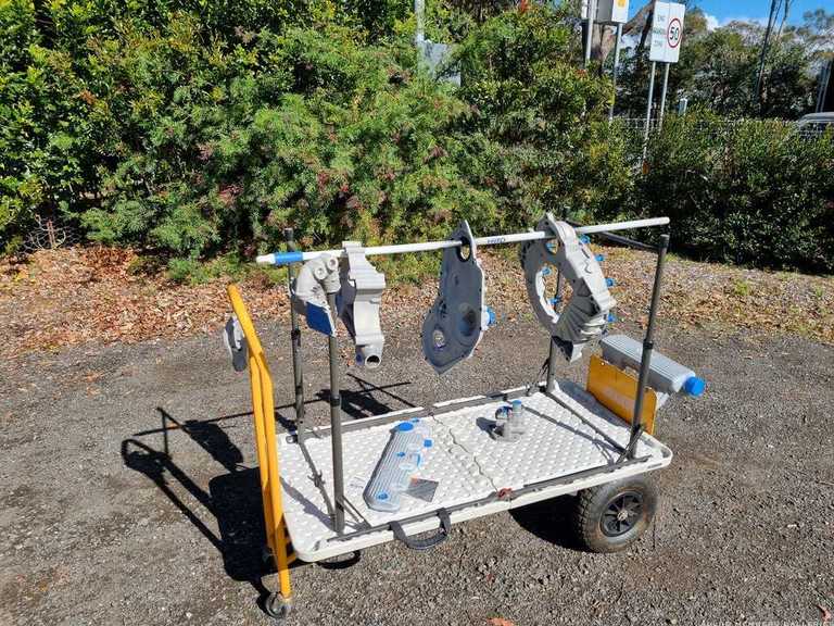
Conveniently, I found that an upturned camping table fit perfectly on my folding hand-cart trolley, and a broom handle through the seal holes gave good access to all surfaces. The inlet manifold I got creative and bolted to the footboard of the trolley.
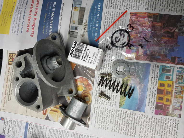
All of the aluminium parts are now done. I pre-assembled a few of the minor ancillaries, such as the thermostat housing complete with new thermostat, and the oil filter head with new waxstat and adaptor and fresh fasteners for the latter.
In the spirit of getting carried away and for safe keeping, I've wrapped them in glad-wrap and tucked them neatly on the shelf. I know they'll get a beating in time, but it seems a shame to let things get scuffed up before I've had a chance to put them on the engine!
[B][I]Andrew[/I][/B]
[COLOR="YellowGreen"][U]1958 Series II SWB - "Gus"[/U][/COLOR]
[COLOR="DarkGreen"][U]1965 Series IIA Ambulance 113-896 - "Ambrose"[/U][/COLOR]
[COLOR="#DAA520"][U]1981 Mercedes 300D[/U][/COLOR]
[U]1995 Defender 110[/U]
[SIGPIC][/SIGPIC]
TopicToaster
To correct the timeline a little, after the blasting and before the painting is when I did the helicoiling and various other repairs to the aluminium parts.
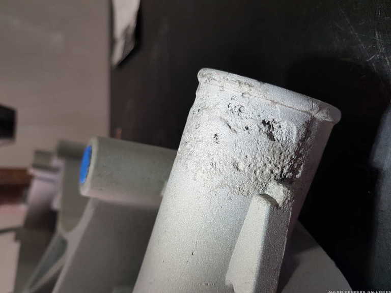
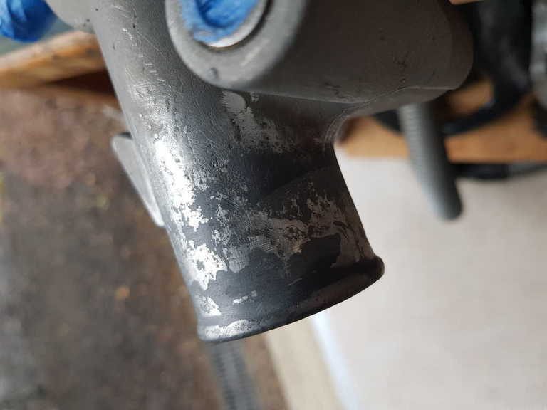
This included the fitting in the water pump housing where the bottom hose connects, which was badly corroded. I briefly flirted with replacing it, but after seeing the price I decided I would make do.
After blasting, the extent of the corrosion became apparent. It was badly and deeply pitted, but not holed and to my mind really just needed sealing up and it would be perfectly fine.
I ended up just forcing JB Weld into the pits and massaging it firmly into every nook and cranny. Once dry, I sanded it back to original size and shape.
I haven't got a photo of it after painting, but you'd never know it was there and it seems rock-solid.
The oil filter housing got a new waxstat. I also replaced the extension piece that it sits into as mine never sealed properly due to some light damage on the inner sealing surface. The bolts for this were also a bit rounded so were replaced. Note that both washers go together on the outer end of the spring. I've read stories of people (perhaps intuitively) attempting to put one at either end, which doesn't work. They aren't actually washers so much as valve components, I guess.
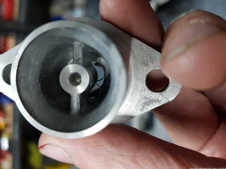
I always make a habit of thoroughly inspecting new parts, and this is why:
The inside of the waxstat adaptor had a nice big piece of swarf from having the thread cut in. Not at all the kind of thing you want circulating straight into a brand new engine!
[B][I]Andrew[/I][/B]
[COLOR="YellowGreen"][U]1958 Series II SWB - "Gus"[/U][/COLOR]
[COLOR="DarkGreen"][U]1965 Series IIA Ambulance 113-896 - "Ambrose"[/U][/COLOR]
[COLOR="#DAA520"][U]1981 Mercedes 300D[/U][/COLOR]
[U]1995 Defender 110[/U]
[SIGPIC][/SIGPIC]
TopicToaster
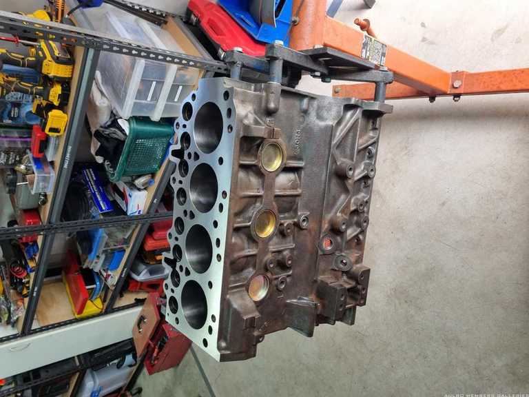
After a little over a month, the very busy little machine shop gave me the call that my block was ready. Being a largely one-man band, this time frame was not unreasonable, and I'm happy with the work they did. For $810, they:
- Chem cleaned block
- Rebored block to match 0.020" oversize pistons
- Honed bores
- Milled block face
- Installed cam bearings (supplied by me)
- Installed core plugs (supplied by me)
- Inspected and linished crankshaft
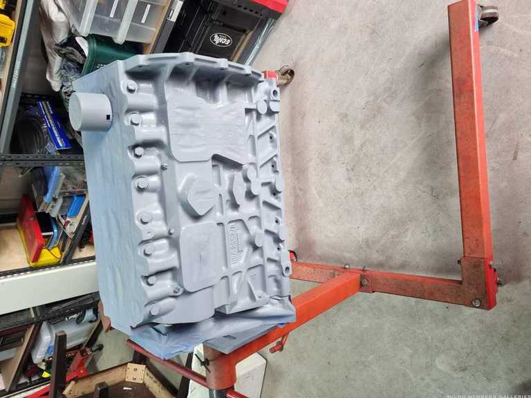
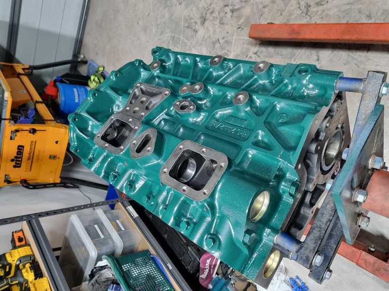
After a tidy up with the wire wheel on the drill, I was keen to get the block in primer and paint.
Why British Racing Green? Three reasons: It's British, it's obviouslya race engine, and the can was in the discount bin at REPCO. Looks good though, and seemed Land Rover appropriate.
[B][I]Andrew[/I][/B]
[COLOR="YellowGreen"][U]1958 Series II SWB - "Gus"[/U][/COLOR]
[COLOR="DarkGreen"][U]1965 Series IIA Ambulance 113-896 - "Ambrose"[/U][/COLOR]
[COLOR="#DAA520"][U]1981 Mercedes 300D[/U][/COLOR]
[U]1995 Defender 110[/U]
[SIGPIC][/SIGPIC]
 Posting Permissions
| Search AULRO.com ONLY! |
Search All the Web! |
|---|
|
|
|


Bookmarks