| "Bottom Row" - pins 1 to 13 (they're numbered from left to right as shown in the photo) |
| 1 |
Red/Green |
Idle bypass valve - circuit 1 |
| 2 |
Brown/Orange |
Power feed to the fuel injection main relay |
| 3 |
Yellow |
Throttle position sensor output/reference - see also 20 and 25 |
| 4 |
Black |
Oxygen sensors (ground) and to the relay that powers their heater coils |
| 5 |
Grey/Black |
Tune resistor (through VIN LA451517 only) |
| 6 |
Yellow |
Road speed input |
| 7 |
Green/Blue |
Coolant temperature sensor (input) - see also 25 |
| 8 |
Purple/Yellow |
Windshield defroster input, if fitted |
| 9 |
White/Light Green |
Diagnostic connector output |
| 10 |
Black/Yellow |
"Check Engine" lamp |
| 11 |
Yellow/White |
Right bank of injectors - cylinders 2, 4, 6 and 8 |
| 12 |
Blue/Red |
Main relay "request" |
| 13 |
Yellow/Blue |
Left bank of injectors - cylinders 1, 3, 5 and 7 |
|
| "Middle Row" - pins 14 to 27 (they're numbered from right to left as shown in the photo) |
| 14 |
Black |
Ground |
| 15 |
Brown |
"Battery" supply |
| 16 |
Blue/Purple |
Fuel pump relay "request" |
| 17 |
Grey/Yellow |
Purge control valve output |
| 18 |
White/Pink |
Diagnostic connector output |
| 19 |
White/Grey |
"Ignition" supply |
| 20 |
Red |
Throttle position sensor (input) - see also 3 and 25 |
| 21 |
Yellow/Black |
Air conditioning thermostat input, if fitted |
| 22 |
Blue/Red |
Air flow sensor (input) - see also 25 |
| 23 |
Blue |
Signal from the LH oxygen sensor |
| 24 |
Blue |
Signal from the RH oxygen sensor |
| 25 |
Red/Black |
Ground side of coolant, fuel, airflow & throttle-position sensors |
| 26 |
Green/White |
Idle bypass valve - circuit 1 |
| 27 |
Black/Grey |
Ground |
|
| "Top Row" - pins 28 to 40 (they're numbered from left to right as shown in the photo) |
| 28 |
Blue/Grey |
Idle bypass valve - circuit 2 |
| 29 |
Orange |
Idle bypass valve - circuit 2 |
| 30 |
Black |
Fault display data |
| 31 |
Black/Green |
Diagnostic connector "request" input |
| 32 |
Grey/White |
Fuel temperature sensor (input) - see also 25 |
| 33 |
Black/Grey |
Air conditioning compressor clutch relay, if fitted |
| 34 |
Orange/Black |
Transmission gear switch signal |
| 35 |
Blue/Green |
Air flow sensor (input) - see also 25 |
| 36 |
Black/Green |
Air conditioning condenser fan output, if fitted |
| 37 |
(Not Used) |
|
| 38 |
Brown/Black |
Fault display data |
| 39 |
White/Black |
Engine speed signal cable (harness includes 6.8k ohm resistor) |
| 40 |
Black |
Ground |


 Reply With Quote
")
 I'll see if there is an easy way to get a pressure gauge into the fuel rail to check.
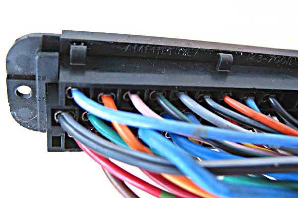

 I was just looking at the prices of fuel pumps on ebay (yes all the cheaper ones don't have the wiring harness on them required for htis car. I wonder if you can just wire the old plug on). Anyway, I'm looking at the pumps and thought .............................. Crap, there is another issue that my problems match. I head out to the shed and unscrew the filler cap ... It was hard to unscrew. The Oring was half way down the threads. With this off the car is running perfectly.


 [/IMG]
Bookmarks