


 Reply With Quote
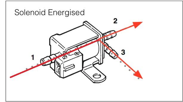
Did you test it with ignition on?.... be aware that the modulator is working with pwm command on the earth path to open and gets 12V ignition live to become "active"(which means closed at the beginning), without ignition on it's like a simple open diaphragm.... it's made so to not get overboost if fuse F2 is blown... sorry i didnt read the document before i posted

 )
)

Bookmarks