
")

 Reply With Quote
The ABR stuff looks pretty much what I had in mind & the aircraft style model looks great. Prolly need to look further in to a clamp option... never been a fan of running huge cables back behind the dash.
Cheers.

 RoverLord
dont go using a shunt to do the measurement, I have a nasty feeling that the resistance of the shunt will throw the management system on the new advanced vehicles.
The kit that I was referring to is now replaced with this one. AC/DC Current Clamp Meter Kit for DMMs - Jaycar Electronics which is out of stock and will also require the addition of a simple volts meter kit to make use of it.
heres the altronics one.
Altronics - Your One Stop Audio Visual & Electronics Supplier
and heres the original silicone chip one.
http://www.siliconchip.com.au/cms/A_30551/article.html
Dave
"In a Landrover the other vehicle is your crumple zone."
For spelling call Rogets, for mechanicing call me.
Fozzy, 2.25D SIII Ex DCA Ute
TdiautoManual d1 (gave it to the Mupion)
Archaeoptersix 1990 6x6 dual cab(This things staying)
If you've benefited from one or more of my posts please remember, your taxes paid for my skill sets, I'm just trying to make sure you get your monies worth.
If you think you're in front on the deal, pay it forwards.
Master
The ABR stuff looks pretty much what I had in mind & the aircraft style model looks great. Prolly need to look further in to a clamp option... never been a fan of running huge cables back behind the dash.
Cheers.
Master
Hey thanks Dave... will check these out now.
 OldBushie
Thanks and thanks Dave, I remember the original project in Silicon Chip. Unfortunately for what I want to measure, the d4’s alternator to cranking battery cable currents, it needs a maximum in access of 180 amps.
Hi Mully, if you go with the kits, wrap everything in electrical type and/or heat shrink, that includes the toroid cores, it won’t change the accuracy of the Hall Effect but it will prevent possible shorts when you try accessing some of the cables around a vehicle.
BTW if you want to use the info gained from the current measurements to control different devices and/or events, while you can use shunts to get accurate current measurements, but because they are installed in the negative circuit, they are not reliable because if you get a short, they can not see it.
Whereas, high side current monitoring is perfect for sensing shorts.
Master
If the amp meter you are referring to is per the link below, it is probably good for an early Defender but as for a current D3/4, I am not so certain. The use of a shunt really bothers me.Originally Posted by Mully

There are two kinds of airplanes, light and heavy. Light is generally piston gasoline; heavy, the jet sort. The electrical systems on most light aircraft are early Edison, so simple even I can understand them and the referenced instrument would work well. It is not the sort of thing I would be installing on my Lear however. Per the other link below, MGL makes instruments for homebuilt aircraft, not always the most advanced, at least electrically.
Also my view is that the D3 electrical system was designed by some laid off AirBus types who were picked up by BMW. The whole wiring system of the D3 just looks more heavy aircraft than it does early Series.
MGL Bat 1
Infinity Singles
Master
Thanks guys.... the Silicon Chip would be great except it is only 80A as mentioned. The other options using a remote volt meter are a bit ordinary and not what I'm after. The MGL units look exactly what I'd like to achieve and if I can sort a decent clamp circuit, I'll put something like that together from scratch if need be.
Challenge number two may be finding a place to locate said gauge!
Drivesafe thanks for your input and I'd love to see you come up with a kit as a solution. I'm quite surprised that after 6 years or so that there isn't a commercial option for the D3/4 on the market, it's such an important piece of information and I shudder at the thought of relying on the alternator in dash 'globe' to tell me I may not get home without a jump start.
The search continues and thanks again one and all.
Master
SupporterWould something like this be suitable for monitoring draw on a 2nd battery (isolated from the main battery by a Traxide SC40)?
http://www.ebay.com.au/sch/i.html?_f...%2B+Shunt+75mV
I'm thinking placing this after my 2nd battery and before my accessories fuse box (installed under the drivers seat). This should give me an indicator of current draw when running my fridge, lights and other bits and pieces from the fuse box? Would this also measure the amount of charge going into the battery when driving or would I need to place the shunt between the SC40 and battery to see charging rate?
Master
If you just want to measure in/out on the one battery, put it in the battery negative lead to the chassis.
If you want to measure the load for one item, you should set up a test lead. Personally I use "rigrunner" type boxes (google it and west mountain radio) and all accessories (non-factory) are run using "powerpole" connectors (normally 30A do nicely) to the rigrunners.
I actually use "rigrunner" as power distribution boards in my trailer as well, so everything is standardised.
OldBushie
Hi Ashes, if you want to get high current amp readings, the simplest way it to fit two of the shunts in parallel and connect to one of them.
Just remember that that the reading you get has to be doubled.
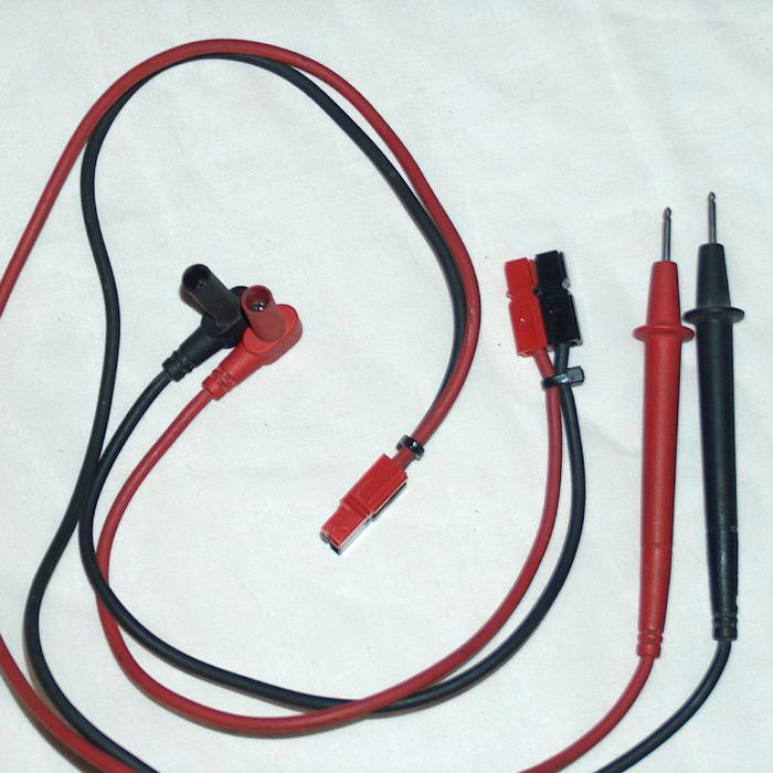
The other way for getting both volt and amp reading is to something like a Doc Watson meter ( se the link below ) fitted with Anderson Powerpoles as gps-au suggested.
Watts Up and Doc Wattson power meters.
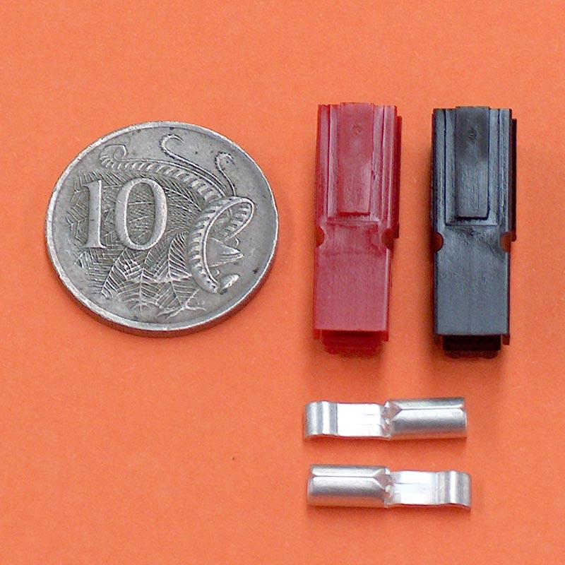
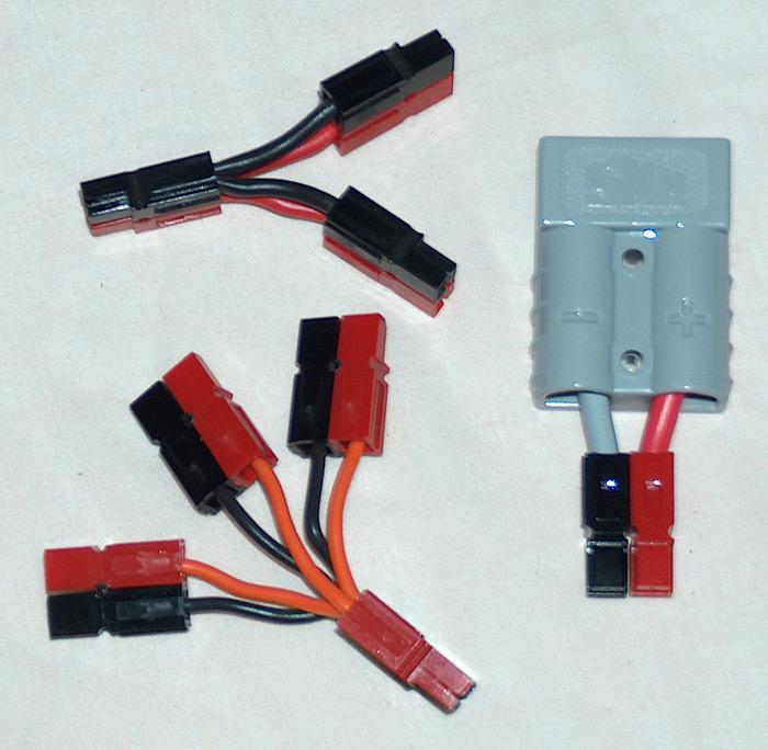
I have made up loads of different cable set ups using the Anderson 15, 30 and 45 amp Powerpoles so I can plug what ever I need to into a set up for testing.
The Anderson 15, 30 and 45 amp Powerpoles all use the same size housing so they are interchangable and all plug together.
Although these meters cam measure up to 100 amps, because the cables connected to these meters is so thin, I rarely use them for loads much greater than 30 to 40 amps max.
Master
SupporterThanks guys, at this time I'm just interested to see the total draw so I can estimate battery life based on what I'm running when camping and more carefully use the "expensive" drawing items. I can run each device independently so I can cycle though each of the devices to see what they are doing.
So to get this clear in my head and based on the following guide which is likely to be pretty standard
http://jaycar.com.au/products_uploaded/QP5588%20User%20Manua.pdf
- place the shunt in the negative/earth cable between the 2nd battery neg terminal and the chassis ground point, connecting it in serial with the 2 large terminals on the shunt
- the digital ammeter has 4 inputs ( +/- power and +/- signal input)
-I can take +/- power from my accessory fuse box or a 9v battery (might put a switch on it so it's not on all the time or use a swith I already have on a digital voltmeter)
- the negative signal input is one of the small screws on the shunt and the positive the other.
With this setup and using a 9v battery for power the only cable I would need to run would be 2 relatively thin wires from the shunt back to the display.
Will the digital display show a "-" when devices are using power and a "+ or nothing" when the aux battery is charging?
Am I missing anything in regards to this?
 Posting Permissions
| Search AULRO.com ONLY! |
Search All the Web! |
|---|
|
|
|

Bookmarks