
Originally Posted by
sniegy

Back of the Headlight. In the plug itself.
From memory Blue/Black R/H or Blue/Slate L/H headlight.
This is where i picked up my high beam switch wire from & many other customers.
Cheers
Just looking at adding my spotties to my D3. How does this work for the relay trigger? There's a constant 12v at the blue/slate lh side headlight on mine
Shane
2005 D3 TDV6 loaded to the brim with 4 kids!
http://www.aulro.com/afvb/members-rides/220914-too-many-defender-write-ups-here-time-d3.html


 Reply With Quote
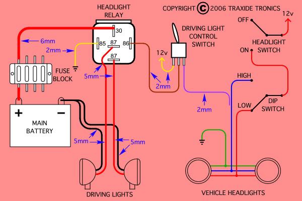


Bookmarks