Page 1 of 2 12 LastLast
Results 1 to 10 of 20

Thread: DT90-L322 Range Rover Dual Battery Kit Installation

  1. #1
    Join Date
    Jan 1970
    Location
    Queensland
    Posts
    7,904
    Total Downloaded
    0

    DT90-L322 Range Rover Dual Battery Kit Installation

    DT90-L322 DUAL BATTERY KIT INSTALLATION.

    It is suggested that you use an Optima D34 Yellow Top Battery with this kit.

    The DT90-L322 Dual Battery Kit contains a pre-wired main module.

    The first cable coming from the DT90 module is the Red input cable which has a small “Z” bracket bolted to the Eye Terminal on the end of this cable.

    This “Z” bracket is used to make the connection to the main Range Rover cable at the fuse panel in the rear of the cargo area.

    The next Red cable coming from the DT90 module has a Plastic Box housing a 50 amp Auto Resetting Circuit Breaker in it. On the other end of the Circuit Breaker is a cable with an 8mm Eye Terminal fitted to it.

    This cable will be connected to the Positive terminal of the Auxiliary battery.

    Coming from the last output of the DT90 module is the Brown Earth wire with an 8mm Eye Terminal, the Red wire Accessories Power output wire with an In-Line Fuse Holder and a 30 amp Red Anderson Power Pole, and the sheathed 4 core wire for the LED In-Cab module.

    Also connected to the 8mm Eye Terminal on the Brown Earth wire is another Brown wire with a 30 amp Black Anderson Power Pole plugged together with the Red Power Pole on the Accessories Output wire.

    The rest of the DT90-L322 kit includes :-

    1 x Battery Terminal Clamp Set

    1 x Short Black Battery Earth Cable.

    1 x M6 x 16mm Bolt

    1 x M6 x 100mm Bolt

    2 x M6 Flat Washer

    2 x M6 Nut

    1 x M6 Nyloc Nut

    1 x M10 Nyloc Nut

    1 x Aluminium Battery Hold Down Bracket

    2 x Short Aluminium “U” Bracket

    1 x Cigarette Power Socket Supply Loom.

    1 x 50 amp Grey Anderson plug and leads.

    2 x Wire Tires

    1 x WARNING Sticker.


    You will need the following tools :-

    6mm Allan Key

    10mm Socket

    17mm Socket

    Large Flat Blade Screwdriver

    Small Philips head Screwdriver

    Hammer

    Small angle grinder.


    NOTE, the Cranking Battery Terminals DO NOT need to be disconnected to install this kit.


    Start by lifting and removing the Spare Wheel Cover, and remove the floor lid and the Fuse Panel Access Cover.

    Using the 6mm Allan Key, remove the two Tire Downs on the driver side of the cargo area.

    Now remove the remove the 4 Hooks, two near the cigarette power socket and two at the corner panel at rear edge next to the tailgate.

    You remove the Hooks by twisting them 90 degrees counter clockwise and then pulling them out.

    There is a spring loaded fold down cover on the bottom edge of the tailgate.

    Go to the driver side of the cover and pull the edge of the cover up till it unclips from it’s hinge. This will take some force.

    You only need to unclip the first section, not the whole cover.

    Now while holding up the edge of the tailgate cover, pull the base of the corner panel up and out then slide the top down and out of the slot in the bottom edge of the shelf panel.

    Next, there is a push in plug holding the bottom rear corner of the panel where the cigarette power socket is mounted.

    This plug is hard to remove so use the large flat blade screwdriver and leaver the plug out from under the panel.

    Unclip and remove the Blue tube housing the safety triangle.

    Get the 10mm socket and remove the 3 nuts that hold down the Black plastic base plate.

    Pull out the bottom corner of the panel with the cigarette power socket in it and then lift and remove the black plastic base plate.

    In the base of the compartment you will find a wire loom. At the forward edge of the compartment, where the loom runs long the bottom and the up the side edge, you will find a plastic wire tire secured in place by a screw protruding upwards from the base of the compartment.

    The screw needs to be removed.


    A Small angle grinder, if available is the easiest way to remove the screw. I also suggest the area be coated with something like liquid gal, to protect the bare metal from rusting.


    With everything stripped down, you can now start installing the Dual Battery System.

    Take the Short Black Cable and the M10 Nyloc from the kit and at the rear edge of the compartment you will see the two bolts that hold the rear bumper in place.


    Secure the 10mm Eye Terminal on the end of the Black Cable to the top bolt, using the M10 Nyloc.

    Get the M6 16mm bolt and place it down through the middle hole in the bracket sticking out from the driver side of the compartment, below the fuse panel.

    Using one of the M6 Nuts, NOT the Nyloc, secure the M6 16mm bolt in place.

    Next, take the M6 100mm bolt and place one of the Short Aluminium “U” Brackets and place it over the bolt so that the “U” faces away from the head of the bolt.

    Now from the bottom of the bracket fixed to the passenger’s side of the compartment, push the bolt up on the inside at the very rear edge of this bracket.

    Position the bolt so the bolt is on the inside of the bracket and one of the Short Aluminium “U” Bracket is on the outside.

    Place the other Short Aluminium “U” Bracket, with the “U” facing downwards, over the end of the M6 100MM bolt and fit it in a similar way to the bottom “U” bracket.

    Using one of the M6 Flat washers and one of the M6 Nuts, NOT the Nyloc, secure the M6 100mm bolt in place.

    Make sure this nut is tightly secured in place, otherwise it will spin when you try the secure the Nyloc nut in place.


    Next get your Optima battery and with the POSITIVE terminal facing towards the front of the RR, place the battery in the compartment.

    While lifting the battery in place, make sure the large wire loom at the bottom of the compartment is right up against the side wall to avoid crushing any of the wires in the loom.

    Before fitting the hold-down bracket, bend the M6 16mm bolt towards the battery. This will make it easier to place the bracket over the bolt when fitting the bracket.

    Now take the battery clamps from the kit and remove both wing nut and bolts and secure the clamps in place in the positions shown in the picture.


    Next, position the Aluminium Hold Down Bracket with the tapered end towards the driver side of the battery.

    Now lift the other end of the bracket up and slide the tapered end under the M6 16mm bolt and position the bolt over the hole in the tapered end.

    Position the other end of the bracket over the M6 100mm bolt and place the M6 flat washer over the bolt and secure down the bracket with the M6 Nyloc.

    With the Hold Down Bracket secured in place, using a hammer, give the bracket a gentle tap to move it towards the driver side. This will make sure the black plastic base plate clears the bracket when it is reinstalled.


    You can now reinstall the black plastic base plate by first positioning the two plugs on the edge on the base plate over the holes in the bracket below the fuse panel.


    Now secure the three nuts back in place.

    Here is a tip, place a piece of paper over the 10mm socket then press the nut down into the socket. This will hold each nut in place while you position it over each bolt.

    Also, once you have located the nut on the bolt, slowly and gently rotate the nut counter clockwise till you fell it drop. This positions the nut back to the same thread position and makes it easier to tighten the nut up. You can now secure the nut in place.

    Fitting the Dual Battery Control Module and cabling.

    Go to the thick red cable connected to the fuse panel and using the 10mm socket, remove the nut, but leave the cable in place.

    Get the “Z” bracket and place it over the bolt on the red cable and replace the nut.


    Now position the DT90 control module next to the wire loom that runs down behind the black plastic base plate at the rear.

    There is a couple wire tires in the kit. You can use these to secure the module in place once the installation is complete.

    Feed the rest of the wires and cable plus the Circuit Breaker Box down behind the black plastic base plate and bring the Thick Red Cable put over the top of the battery.

    Now get the Grey Anderson plug and using one of the battery clamp bolts, secure the 8mm Eye Terminals on Anderson Plugs Red cable and the Red cable coming from the Circuit Breaker Box, to the battery’s Positive battery clamp.

    Now get the end of the Earth cable, the Black cable connected to the Grey Anderson plug and the 8mm Eye terminal, with the two thin Brown wires connected to it and using the other Battery Clamp Bolt, secure the three Eye Terminals to the Negative Battery Clamp.

    WIRING UP THE LED MODULE.

    Open the LED module and you will see an LED at one end of the PCB and a Green 4 Way Screw Terminal Block.

    Using a small Philips Head Screwdriver, starting closest to the LED, fit the Red wire first, then the White, Blue and Black last.

    NOTE, these wire are safe and can contact each other without causing any problems.

    Switch Settings.

    Switch 1 controls the Cranking Battery Cut-Out Voltage level.

    OFF = 12.0v ( SHEARED mode )

    On = 12.65V ( IGNITION mode )

    Switch 2 controls the Accessories Cut-Out Voltage level.

    OFF = 11.8v ( for Flooded Wet Cell Batteries )

    ON = 11.6v ( for AGM Batteries )

    The recommended settings are 1 = OFF, 2 = ON.

    Once wired and the Switches set, Tire a knot in the 4 core wire to stop it being pulled from the Module case and use the two small black screws and secure the Top to the base.


    The LED on the module should be giving one short Green flash every two seconds.

    Leave the LED module loose for now.

    Next, go in behind the cigarette power socket and push the front end, that’s up behind the light fitting.

    Push on the back of the fitting until you can take hold of it from the outside.
    Pull the whole out and remove the plug from the back of the cigarette power socket.

    Get the two wire loom from the kit and push the terminal connected to the wire with the RED trace, onto the centre terminal of the cigarette power socket, then push the other wire onto the outside terminal.


    Reinstall the cigarette power socket by first fitting the cigarette power socket end into the rear of the slot and then pushing on the light at the front, until it clips back in place.

    On the other end of this two wire loom is a Black and Red 30 amp Anderson Power pole connector. Run this end of the loom down behind the front edge of the black plastic base plate and then up over the Battery Hold Down Bracket, to the Anderson Power Poles connected to the isolator’s wiring.

    Connect the Power Poles together and the Dual Battery installation.

    Reinstall the rear corner panel by locating the top edge of the corner panel up into the slot under the shelf panel.

    You may need to slide the top edge back and forth until you have it in the correct position, lined up with the two holes where the hooks go.

    Lift the tailgate cover and move the base of the corner panel back in place.

    Reinstalled the hooks and then bang the edge of the tailgate cover so it clips back in position.

    Now go to the panel with the cigarette power socket in it and at the bottom, locate the small plug over the hole. Make sure this is in the correct position, then tap it with the hammer to drive it home.

    Refit your two Tire Downs.

    Now to the LED module.

    You can chose to leave this loose or permanently fix it somewhere where you can see it from outside the RR.

    By leaving it loose, you can tuck it in behind the Fuse Panel Access Cover when you are not using the system and hang it over the top of the cover when you need to see how your batteries are going while off camping.


    Put the floor lid back and you only need to fit the WARNING sticker on your cranking battery and the whole installation is finished.

    Last edited by p38arover; 6th November 2023 at 01:25 PM.

  2. #2
    Join Date
    Jan 2012
    Location
    Sunshine Coast, Australia
    Posts
    128
    Total Downloaded
    0
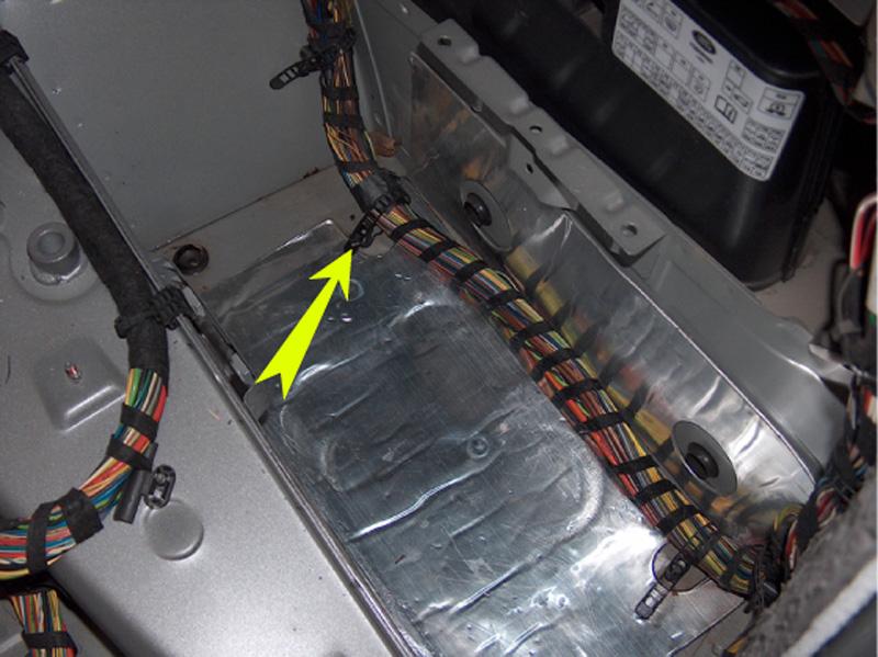
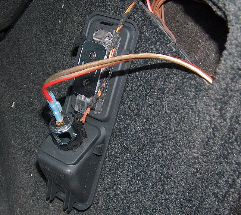
    A tip for others, the carpeted panel on the drivers side with the 12v port does not need to come out. Just the rear bottom corner comes out to allow the black plastic to be removed.

    Its not explained incorrectly above, just an error I made.

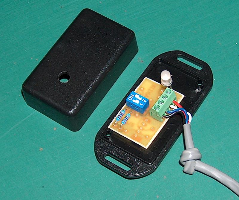
    Also ensure you knot the grey cable (going into the led case) before you wire it up, otherwise you'll have to undo them all to knot it.

  3. #3
    Join Date
    Jan 1970
    Location
    Queensland
    Posts
    7,904
    Total Downloaded
    0
    Hi Craig and it is better to knot the cable after connecting the 4 wires.

    You can make the knot in the cable with the switch base wired in and while it's a bit tricky to move the knot to where you need it, by having the base connected, you can position the knot in the correct place to allow the cover to go on but the knot stops the cable from being pulled from the screw block terminals.

    BTW I'll place the operating info up in this thread as soon as I complete the artwork for the LED operations.
    Last edited by p38arover; 1st February 2016 at 10:08 AM.

  4. #4
    Join Date
    Nov 2012
    Location
    Gawler
    Posts
    30
    Total Downloaded
    0

    Quote please for this kit?

    Please quote on the unit
    Thanks
    Tony
    Last edited by p38arover; 1st February 2016 at 10:09 AM.

  5. #5
    Homestar's Avatar
    Homestar is offline Super Moderator & CA manager Subscriber
    Join Date
    Aug 2010
    Location
    Sunbury, VIC
    Posts
    20,105
    Total Downloaded
    0
    Hi Boxpacker, check out this thread - http://www.aulro.com/afvb/verandah/1...ttery-kit.html

    They are $299 and well worth the dollars. This is a very well thought out kit that is a snap to fit. After sales support from Drivesafe is first class.

    Cheers - Gav
    If you need to contact me please email homestarrunnerau@gmail.com - thanks - Gav.

  6. #6
    Join Date
    Jan 1970
    Location
    Queensland
    Posts
    7,904
    Total Downloaded
    0
    Thanks Gav.

    Hi Boxpacker and the AULRO members price is $265

  7. #7
    me48409 Guest

    Where to buy

    Hi there. How do I go about buying one of these kits?

  8. #8
    Homestar's Avatar
    Homestar is offline Super Moderator & CA manager Subscriber
    Join Date
    Aug 2010
    Location
    Sunbury, VIC
    Posts
    20,105
    Total Downloaded
    0
    Quote Originally Posted by me48409 View Post
    Hi there. How do I go about buying one of these kits?
    PM Drivesafe - he'll sort you out. He will see your post soon enough as well I would think.

    To do this, click on his username in the post above yours and you will see 'send a private message to Drivesafe' - click on that, and its like sending an email from there. Fill in the title box and then ask him how you order one.
    If you need to contact me please email homestarrunnerau@gmail.com - thanks - Gav.

  9. #9
    Join Date
    Jan 1970
    Location
    Queensland
    Posts
    7,904
    Total Downloaded
    0
    Hi and thanks bacicat.

    Hi me48409 and welcome to AULRO.

    Try this link. Should give you all the info you need and you can phone me on 07 5569 2557, day or evening if you need any more info.

    http://www.aulro.com/afvb/verandah/1...ttery-kit.html

  10. #10
    RR44TDV8 Guest
    Hi Drivesafe,

    I have a MY12 TDV8 Range Rover vogue ad I have 3 deep cycle batteries in my possession........all new Century Yuasa batteries.

    I want to buy a dual battery system for the car from you but I also need some more info..........I am building an expedition trailer and I want to put two house batteries on it as well. so, two batteries in the car and two on the trailer.

    Could you send me:

    A price for what I need to buy from you to make all this happen and if this isn't stretching the new friendship too far, a schematic of how you suggest I should wire to the trailer? I can do all the accessory wiring from the batteries back on the trailer but I am not too sure on how to get the car to manage all 4 batteries whilst driving to the destination. I will charge the trailer batteries with a solar panel once at site.
    Best regards and a big thank-you in advance
    Grant

Page 1 of 2 12 LastLast

Bookmarks

Bookmarks

Posting Permissions

  • You may not post new threads
  • You may not post replies
  • You may not post attachments
  • You may not edit your posts
  •  
Search AULRO.com ONLY!
Search All the Web!