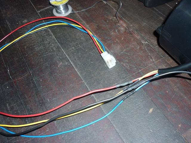
The earth wire to the controls was originally separate and there was a spare socket in the plugs so I couldn't see any reason why it couldn't be included.
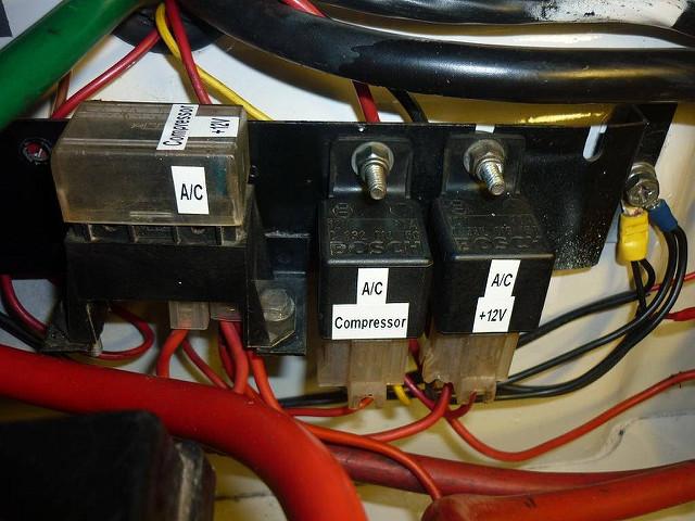
Now the tricky bit (for me anyway). I've placed two relays in the battery box (actually the relays from the original A/C system).
The first is for the compressor solenoid. My local A/C place which is completing the installation told me to just run "a wire" into the engine bay. I am going to assume they will activate both the compressor solenoid and the condenser fan off this wire. However, the relay is the type with two 87 terminals so the option is there to run two separate wires.
The second relay I am using to activate 12 volt power to the evaporator/fan power switch when the ignition is "on" (so the A/C can't be switch on when the engine is off). As to where exactly I'm getting the activation from right at this point isn't clear to me. I'm thinking I need to tap into one of the white wires that is the ignition switch side of the fuses for things such as the gauges, tail/reverse lights, etc. I'm really trying to avoid going up behind the dash because I'm
very over feed wiring through there

. Any advice or opinions will be gratefully received.


 Reply With Quote
.


Bookmarks