Page 41 of 82 FirstFirst ... 31394041424351 ... LastLast
Results 401 to 410 of 812

Thread: Stirlsilver's Disco Ute Project

  1. #401
    Join Date
    Sep 2007
    Location
    Kiwiland
    Posts
    7,246
    Total Downloaded
    0
    Quote Originally Posted by stirlsilver View Post
    Thanks for the suggestion Doug, I appreciate it. I've actually been emailing ARE in Brendale QLD about the intercoolers. I asked them about what options I have available to weld two cores on to either side of the plenum. Below was the response:

    There is not a perfect pair of intercoolers that will fit in your vehicle. I did some quick computer modeling & with a 3.9 L engine, 4500 rpm & 12psi boost you have 563cfm & 26 kw (1509btu) of heat to get rid of to work at good efficiency.
    With 2 of 255 x 300long x 55mm cores the air speed through the core is 64.2 kph for 0.017 secs. 400mm long gives the same speed for 0.022 secs.
    With 2 of 255 x 300 x 73mm cores the air speed is 46.7 kph for 0.023 secs.
    As a very generalized, average, ball park figures 70 kph for 0.025 secs. id good. You need a 73mm core or 300x300x56mm core.


    So I need to think if I want to go to all the hassle to fit in a thicker or wider core. Because the way the plenum is at the moment, I think I only have an area of 60mm x 255mm to weld on a core. I could go all out and get a new plenum welded up, but that is going to add more $$ and I'm not sure how much more performance going from a 255 x 55mm to 255 x 73mm core will add? I need to think about it some more.
    Here is where I am at with an intercooler for my diesel (been running up to 24psi without one)


    My requirements at 4000rpm and ~33psi boost are 500CFM, boost temp of ~190C and heat rejection required of about 33kw.
    So not that far away from yours.

    I've looked at putting an intercooler in the front behind the grille, using water/air and even top-mount. But decided all those options are rubbish.
    Instead I plan to move the AC condensor forward, install a narrower radiator back 25mm from the original and this leaves space for an intercooler of up to 800mm total width with a 600x400x50mm core.

    You can see in the pic above that I drew up what I considered an indeal intercooler to fit that space and a narrower radiator that would package with it. Inlet/outlets right at the top corners are perfect for my setup.

    I was astounded to find the RS500 Cosworth aftermarket intercoolers are exactly that. Various thicknesses are available, but the cores are 600x400x50 on most and inlet/outlets at the top corners in 2.5 or 3" depending on the seller.
    They are about 200 quid including freight on ebay UK and a lower height alloy radiator to work with them is about the same money.
    You might need more radiator cooling than that, but for me it's looking ideal.

    I ran through a set of calcs over the weekend and I think I can take out over 70% of the heat at that 500CFM and 33psi operating point. I am limited by max fuel so it looks like I can drop the boost to about 29psi due to the extra cooling, this extra density drops the volume flow a little and should get me into the high 70's for heat rejection. Outlet temps around 55C.

    *edit*
    Speed through the cores, about 11m/s.

  2. #402
    Join Date
    Jun 2007
    Location
    Oatley, NSW
    Posts
    974
    Total Downloaded
    0
    Nice work with the model there Doug! Also thanks for the info on what you have found so far with intercooler sizes. I think I will go for the 73mm thick cores from ARE, I'll decide in the coming days. Not sure if you realized - i'm doing a top mount intercooler so I won't be touching the radiator.

    I've been trying to dream up a way to have a system so that at low speed thermo fans force air over the intercoolers and at high speed the air is rammed in due to velocity bypassing the thermo fans and going through the intercoolers. But I haven't been able to figure out a simple way without doing a very complicated 2 way valve...

    Anyway, I was only able to spend 5 hours in the workshop this weekend. It firstly involved me getting the engine running on MS3 with MS3 controlling the EDIS module advance angle - I got that sorted.

    Then I needed to flash the MS to the latest development code so that I have access to fuel temperature and pressure correction - this is necessary so that the change in pressure and temperature of the LPG vapour can compensated in injector opening times. Anyway, I got the engine successfully running with that code so I can now proceed with the next bits.

    The next step in getting the engine sorted is a cam angle position sensor. I found on some other forums that the Ford 3.0L V6 cam position sensor makes an ideal candidate.

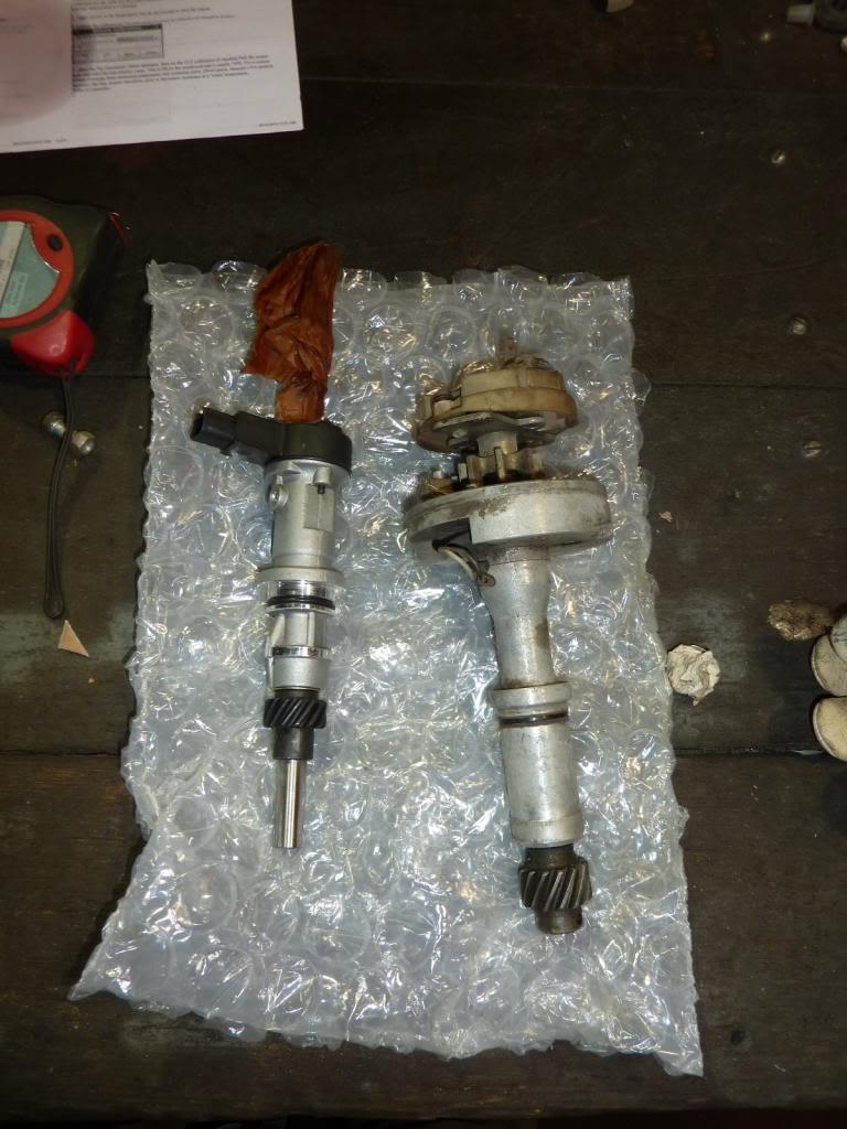
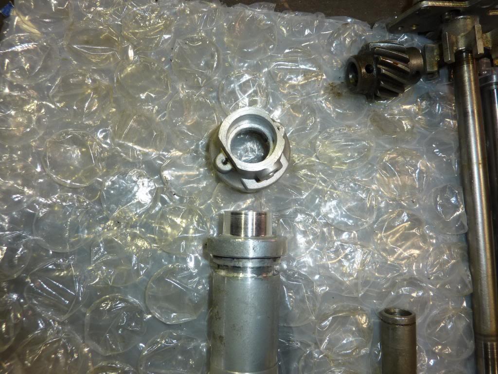
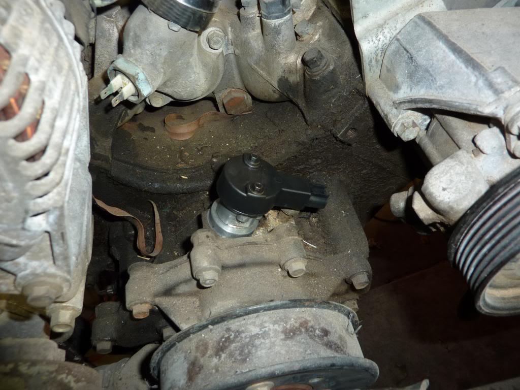
    Here is the Ford Cam sensor beside the Rover distributor:
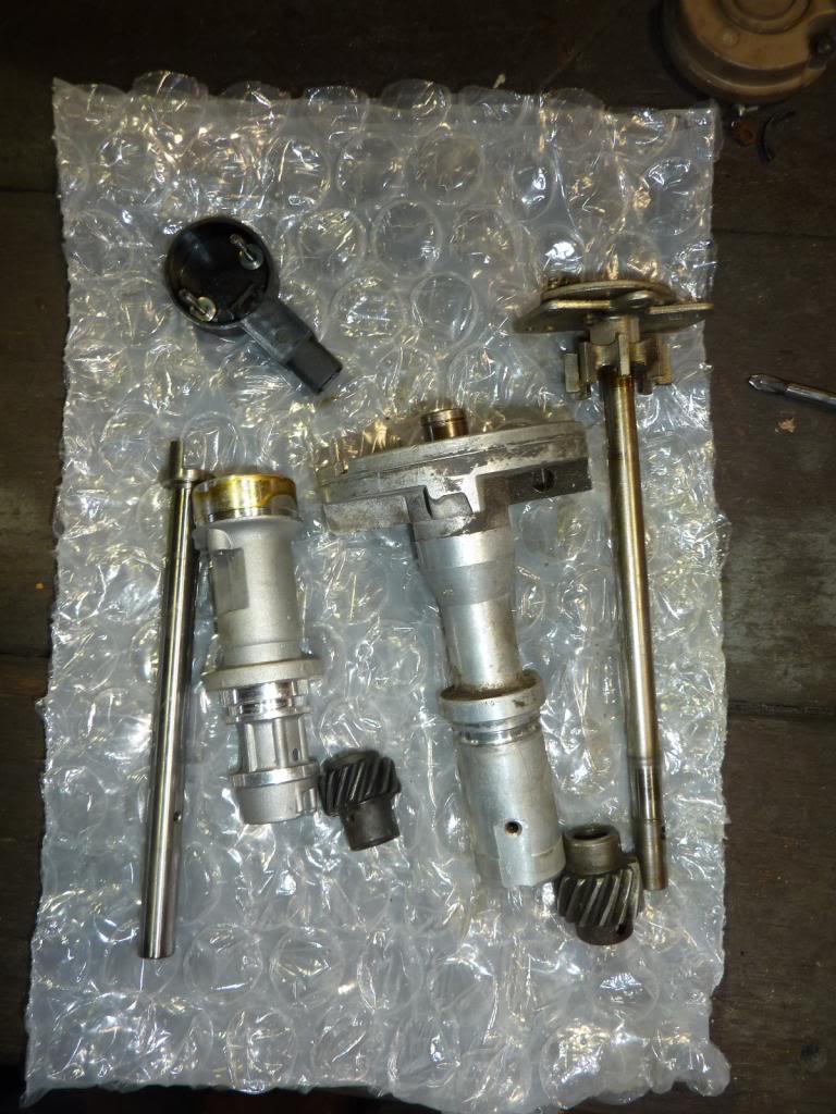
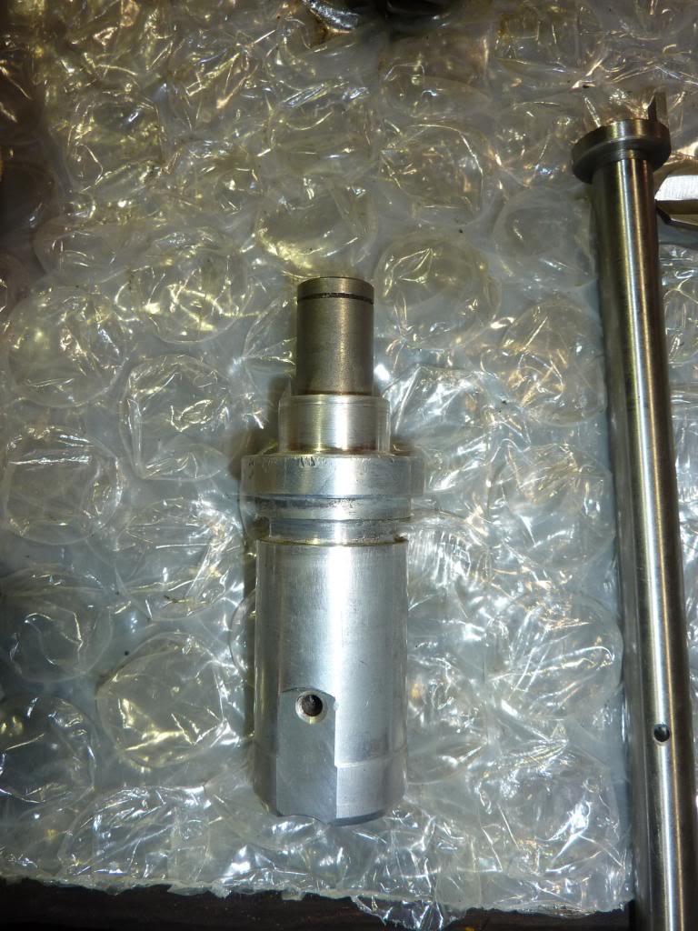
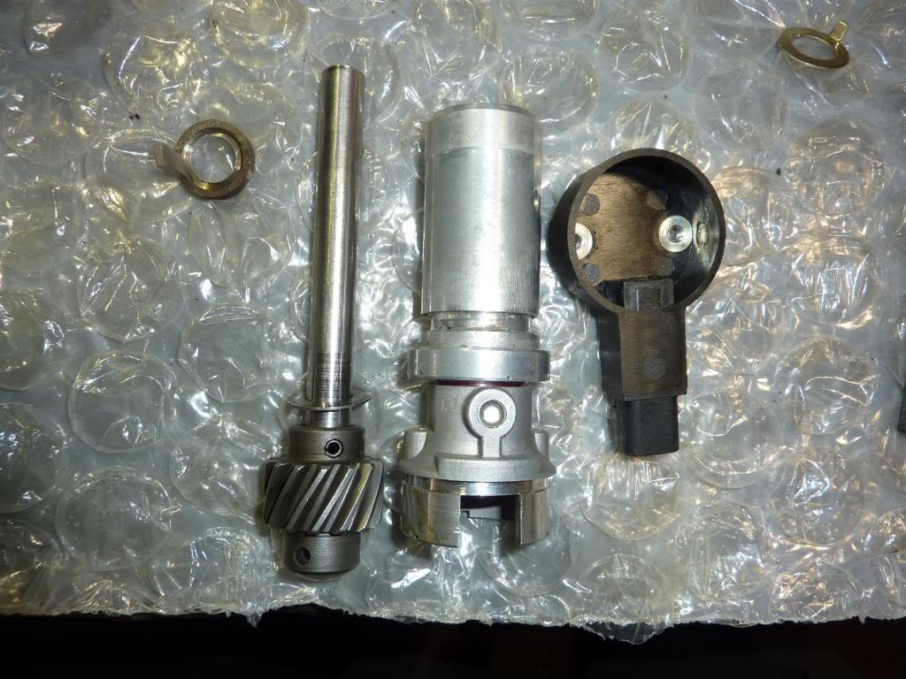

    Disassembly:


    I jumped on a lathe and parted off the top portion of the Ford Cam sensor and the bottom portion of the rover distributor:


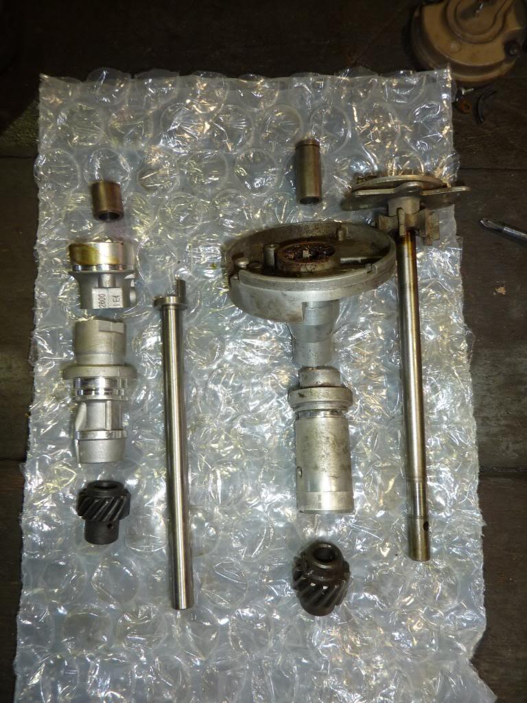
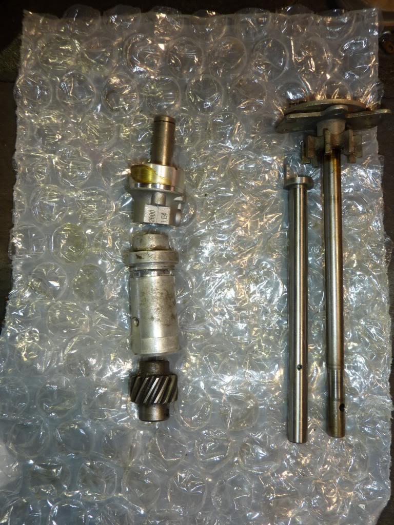
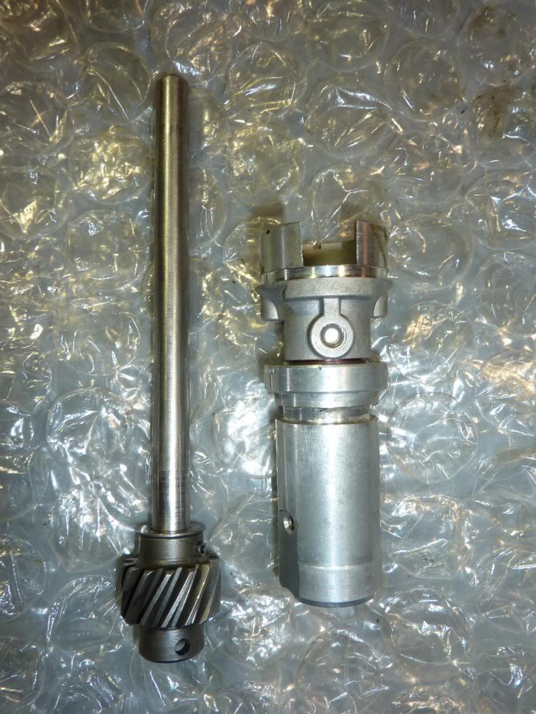
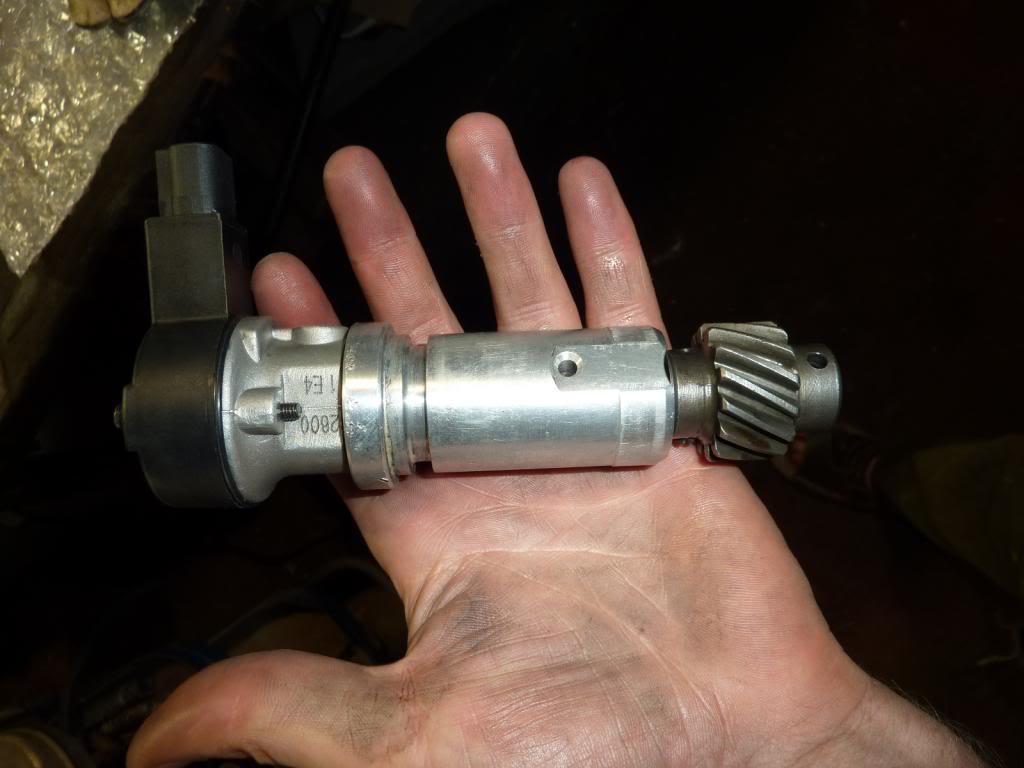
    This is how everything will be put back together:


    From top to bottom:
    Rover top shaft bush
    Ford top housing
    Rover bottom housing
    Rover Drive gear & shaft

    That's all I had time to do, next week i'll continue the machining & hopefully finish the cam position sensor.

    Questions & a favour
    1. Does anyone have a spare Edis 8 connector? - I broke the clips on mine
    2. Does anyone have a connector to suit the Ford 3.0L V6 cam sensor??
    3. Does anyone have an old windows XP/7 laptop that I could borrow? - I'm using my computer (Surface Pro 2) but it's covered in magnets which is bad in a workshop with iron filings everywhere!
    Stirling

  3. #403
    Join Date
    Sep 2007
    Location
    Kiwiland
    Posts
    7,246
    Total Downloaded
    0
    I owned a turbo diesel van with a top-mount intercooler that had ducts attached to the bonnet.
    These scooped air just above and forward of the radiator (high pressure zone) and transferred along and down through the core mounted above the engine.

    I think current Prado and 200 series do the same thing. That in combination with fans sucking underneath should do the job.

    Keep up the good work.

  4. #404
    Join Date
    Nov 2007
    Location
    Sydney - Carlingford
    Posts
    80
    Total Downloaded
    0
    You could look at having a closed circuit for your fan(s) that is opened when a certain speed is reached - this could be activated by an air speed sensor, but I don't know if they can be calibrated down to highway speeds nor how it could be linked to open a switch rather than give a gauge reading. Any aircraft engineers out there? My alternative thought would be revs based from coil maybe, but it would be too erratic due to gear ratios to be useful IMHO.

    Really enjoying this thread - thanks for sharing!
    It's better to regret the things you've done than those you haven't!

  5. #405
    Join Date
    Jun 2007
    Location
    Oatley, NSW
    Posts
    974
    Total Downloaded
    0
    Quote Originally Posted by Dougal View Post
    Keep up the good work.
    Thanks Doug

    Quote Originally Posted by Tyresqueal View Post
    You could look at having a closed circuit for your fan(s) that is opened when a certain speed is reached - this could be activated by an air speed sensor, but I don't know if they can be calibrated down to highway speeds nor how it could be linked to open a switch rather than give a gauge reading. Any aircraft engineers out there? My alternative thought would be revs based from coil maybe, but it would be too erratic due to gear ratios to be useful IMHO.
    My original thought was to use the aftermarket cruise control sensor that is fitted to the car on the drive shaft to control the thermo fans with the ECU. So when you are at high speed they simply turn off. The problem is that a fan which is off creates a fair bit of drag when air tries to flow past it. Hence why I was trying to think of a way to have fans for low speed and a direct air path (bypassing the fans) at high speed. I'm starting to lean towards simply having the fans on all of the time regardless of what speed you are doing

    Aircraft engineers? I have a degree in Aeronautical Engineering though I don't work in that industry.

    Quote Originally Posted by Tyresqueal View Post
    Really enjoying this thread - thanks for sharing!
    Thanks for reading!

    Just a quick update - I've made headway in putting together the peak and hold injector drivers. The home made board in the middle inverts the grounding signal from the ECU to a 0-5V signal which the peak and hold board needs.

    I hope it will work reliably, if this fails the engine will shut down... or loose a cylinder or two.

    Stirling

  6. #406
    slug_burner is offline TopicToaster Gold Subscriber
    Join Date
    Jul 2007
    Location
    Melbourne
    Posts
    4,024
    Total Downloaded
    0
    Do you have to drive the peak hold off/reset it according to the fuel required?
    Quote Originally Posted by benji View Post
    ........

    Maybe we're expecting too much out of what really is a smallish motor allready pushing 2 tonnes. Just because it's a v8 doesn't mean it's powerfull.

    One answer REV IT BABY REV IT!!!

  7. #407
    Join Date
    Jun 2007
    Location
    Oatley, NSW
    Posts
    974
    Total Downloaded
    0
    Quote Originally Posted by slug_burner View Post
    Do you have to drive the peak hold off/reset it according to the fuel required?
    I'm not sure what you mean? MS will be controlling the injector timing directly through this board. I'm not looking forward to doing the maths to calculate injector open times and then including the corrections for gas temperature & pressure.

    Anyway, more progress.
    The upper and lower pieces were machined for an interference fit:


    I reused the top bush from the rover distributor and machined out the inside of the assembly to insert it. Again it was an interference fit. I inserted the bush by heating up the aluminium assembly and then pressing it in. This photo shows it before I machined the bush down to the correct length:


    I joined the upper and lower sections in a similar manner. I heated the top piece up and used some thread locker on the lower section. And then pressed them together. I don't think they will come apart any time soon:


    Just before the final assembly. The original rover shaft machined down to length and the Ford trigger wheel was bored out:


    The finished article:


    A quick trial on the spare motor. It all fits quite nicely:


    On another note, I also finished the injector driver board and tested it. It works beautifully with it regulating to the correct currents. I forgot to take a photo of the whole unit completed with the connector. But you get the idea :


    Tomorrow I am picking up the tray frame and bull bar from the powdercoater
    Stirling

  8. #408
    slug_burner is offline TopicToaster Gold Subscriber
    Join Date
    Jul 2007
    Location
    Melbourne
    Posts
    4,024
    Total Downloaded
    0
    Peak hold circuits are used to extend a short peak. They can either be reset by a counter a certain number of clock cycles later or can be reset by some other event. I do expect the MS to take control of the amount of fuel delivered. I just do not know how the MS will do it, keep extending the pulse or by turning it off.

    All good, just thinking out loud.
    Quote Originally Posted by benji View Post
    ........

    Maybe we're expecting too much out of what really is a smallish motor allready pushing 2 tonnes. Just because it's a v8 doesn't mean it's powerfull.

    One answer REV IT BABY REV IT!!!

  9. #409
    Join Date
    Jun 2007
    Location
    Oatley, NSW
    Posts
    974
    Total Downloaded
    0
    Quote Originally Posted by slug_burner View Post
    Peak hold circuits are used to extend a short peak. They can either be reset by a counter a certain number of clock cycles later or can be reset by some other event. I do expect the MS to take control of the amount of fuel delivered. I just do not know how the MS will do it, keep extending the pulse or by turning it off.

    All good, just thinking out loud.
    As I understand it, solenoids require a high current to open them but a much lower current to hold them open. Peak & Hold board do this by giving a peak current a the start and then tripping to a much lower holding current. This keeps injectors responsive and avoids them overheating.

    The way I have configured these boards is that they give a 5.5A peak to the injector and then hold at 1.3A. The graph below shows how a Peak & Hold board works, it does include a timer for when battery voltage is low during cranking too. All MS does is just command when the injector opens, and when it closes. The Peak & Hold board manages the current.

    Stirling

  10. #410
    slug_burner is offline TopicToaster Gold Subscriber
    Join Date
    Jul 2007
    Location
    Melbourne
    Posts
    4,024
    Total Downloaded
    0
    The injectors have to be driven hard to ensure they turn on or off and don't dribble fuel by being somewhere in between on and off.

    Keep it up, I am sure the followers of this thread are all learning a lot.
    Quote Originally Posted by benji View Post
    ........

    Maybe we're expecting too much out of what really is a smallish motor allready pushing 2 tonnes. Just because it's a v8 doesn't mean it's powerfull.

    One answer REV IT BABY REV IT!!!

Page 41 of 82 FirstFirst ... 31394041424351 ... LastLast

Bookmarks

Bookmarks

Posting Permissions

  • You may not post new threads
  • You may not post replies
  • You may not post attachments
  • You may not edit your posts
  •  
Search AULRO.com ONLY!
Search All the Web!